GB - 11
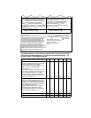
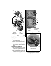
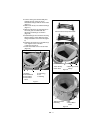
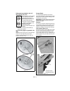
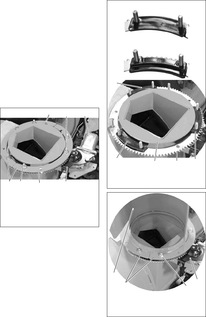
2. Turn the chute gear until the solid pin is
towards the rear of the unit and a
threaded stud aligns with the chute motor
(Figure 7).
3. Remove the six (6) nuts and two half rings
(Figure 7).
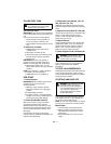
4. Make sure the three (3) chute clamps on
the chute gear are underneath the
discharge chute flange as shown in
(Figure 8)
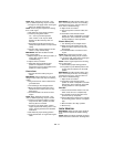
5. Install discharge chute on blower housing
with the opening of the discharge chute
facing towards the front of the unit (Figure
9).
6. Install two (2) half rings on unit with six (6)
nuts. Tighten nuts to 120 lbf-in.
(13.56 N•m) (Figure 9).
7. Install chute motor cover on chute motor
(Figure 9).
Figure 7
1
6
7
5
2
4
3
1.Solid Pin
2.Threaded Stud
3.Chute Motor
4.Chute Motor
Cover
5.Chute Ring
6.Nut
7.Half Ring
Figure 8
1
5
2
4
3
1.Chute Clamp
2.Chute Gear
3.Discharge Chute
Flange
Correct Chute Clamp Orientation
Incorrect Chute Clamp Orientation
Figure 9
1
2
3
1.Discharge Chute
2.Half Ring
3.Nut
4.Chute Motor
Cover
4


