9 - 26
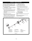
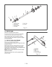
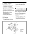
9.1 AUGER/IMPELLER REMOVAL
Place unit in the Belt Service Position.
1. Remove three nuts holding pulley to hub and
remove pulley and key.
2. Loosen set screw in hub and remove hub.
3. Remove three nuts holding bearing flange to
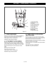
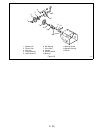
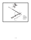
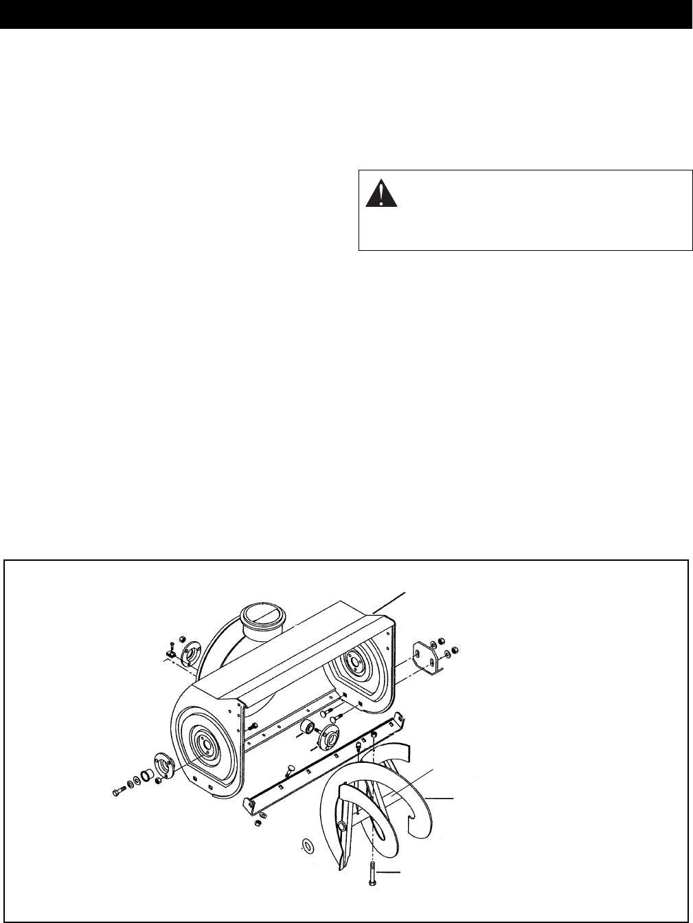
housing and remove bearing flange (Figure 19).
4. Remove two cap screws and lock washers on each
side of blower housing holding rake shaft in
position and remove bushing.
5. Remove three lock nuts attaching bearing support
to housing and remove bearing support.
6. Grasp auger assembly and pull gear case and
auger/impeller assembly free of housing.
7. Drive roll pin out of shaft ends, remove shear bolts
and remove auger from shaft.
8. Check all parts for wear or replacement.
9. Assemble using reverse procedure.
9.2 SCRAPER BLADE
IMPORTANT:
If blade wears too far auger/impeller
housing may be damaged.
Scraper blade is adjustable to compensate for wear.
To adjust scraper blade:
1. Tip unit back onto handlebar and support the
housing.
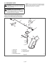
2. Loosen retaining blade nuts (Figure 19).
3. With runners adjusted to their full up position,
reposition scraper blade down, flush with runners.
4. Tighten lock nuts.
9.3 SHEAR BOLTS
IMPORTANT:
Use only Ariens shear bolts for
replacement. Use of any other type of shear bolt may
result in severe damage to unit.
Occasionally an object may enter auger/impeller
housing and jam auger, breaking shear bolts which
secures auger to shaft. This allows auger to turn freely
on shaft preventing damage to gear drive.
To replace shear bolt:
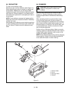
1. Slide auger outward against roll pin and align hole
in shaft with hole in auger (Figure 19) (holes in
shaft for roll pins and shear bolts line up).
2. Drive the new shear bolt through hole (if shear bolt
was broken this will drive remaining part from
shaft).
3. Secure with nut.
SECTION 9 - AUGER/IMPELLER
WARNING:
Stop engine, remove key, wait for
moving parts to stop and remove wire from
spark plug before leaving operator’s position
and attempting to maintain or inspect auger.
1. Blower Housing
2. Scraper Blade
3. Rake
4. Shear Bolt
5. Bearing Flange
6. Bearing
Figure 19
3
4
2
1
5
6


