7 - 23
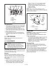
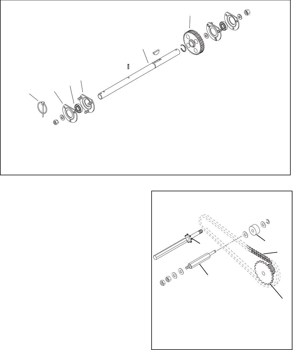
7.4 DRIVE CHAIN
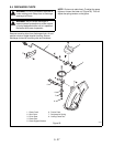
Place unit in Upright Service Position.
To remove link from chain and chain from sprocket:
On the continuous chain grind off end of rivet.
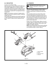
When replacing chain, be sure retainer clip faces
center of unit and is well seated in grooves of master
link (P/N 00004100).
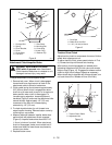
7.5 DRIVE CHAIN ADJUSTMENT
Place unit in Upright Service Position.
If unit is difficult to push because of a tight drive chain,
proceed as follows:
Adjust chain tension by loosening two nuts on idler
shaft. Adjust hex shaft up or down in slot to obtain
proper tension (chain should be snug). Retighten both
nuts. Torque to 170-180 inch lbs.
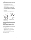
NOTE:
Check interlock mechanism to ensure proper
operation as follows:
Check both clutches to be sure they operate freely
without binding
1
2
3
4
5
6
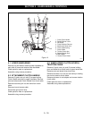
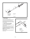
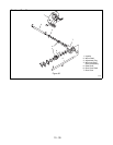
1. Bearing Flange
2. Ball Bearing
3. Bearing Flange
4. Axle Shaft
5. Spur Gear
6. Pin Lock
Figure 15
PS0612
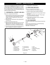
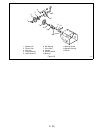
1. Hex Shaft
2. Hex Shaft
3. Idler
4. Roller Chain
5. Pinion and Socket
Figure 16
2
5
3
4
1


