GB - 9
Tools Required
• Adjustable wrench
• Petroleum jelly or dielectric grease.
Unpack Unit
Remove unit and all other components from
the shipping container. Engage transmission
bypass lever (see MOVING UNIT
MANUALLY on page 14). Push unit from
container onto a level surface. Disengage
transmission bypass lever.
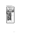
Connect Battery
See Battery Removal and Installation on
page 21 and perform steps 2 and 3 in the
installation section.
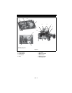
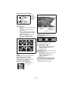
Place Unit in Operating Position
(Figure 3):
NOTE: The seat is shipped with the seat
positioned as far back as possible.
1. Tip seat forward and adjust the seat as
needed (see TIPPING SEAT
FORWARD on page 17 and SEAT
ADJUSTMENT on page 17).
2. Remove eccentric spacers and rotate
steering levers to the operating position.
Reinstall spacers. Do not tighten.
3. Adjust steering levers (see ADJUSTING
STEERING LEVERS on page 22).
Check Engine Oil Level
Refer to Engine Manual.
Check Tire Pressure
See SPECIFICATIONS on page 29.
Level Mower Deck
See LEVELLING AND ADJUSTING PITCH
OF MOWER DECK on page 18.
Fill Fuel Tank
See FILLING FUEL TANK on page 13.
Check Safety Interlock System
See Safety Interlock System on page 12.
ASSEMBLY
WARNING: AVOID INJURY.
Read and understand the entire
Safety section before proceeding.
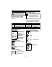
CAUTION: Avoid injury!
Explosive separation of tire and
rim parts is possible when they
are serviced incorrectly:
• Do not attempt to mount a
tire without the proper
equipment and experience
to perform the job.
• Do not inflate the tires
above the recommended
pressure.
• Do not weld or heat a
wheel and tire assembly.
Heat can cause an
increase in air pressure
resulting in an explosion.
Welding can structurally
weaken or deform the
wheel.
• Do not stand in front or
over the tire assembly
when inflating. Use a clip-
on chuck and extension
hose long enough to allow
you to stand to one side.
WARNING: Safety interlock
failure and improper operation of
unit can result in death or serious
injury. Check system before each
use to make sure it is functioning
properly.


