GB - 21
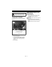
1. Remove mower blade from unit (see
REPLACING MOWER BLADE on
page 20).
Ariens recommends having mower blades
sharpened by a professional. Contact your
Ariens dealer.
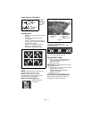
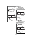
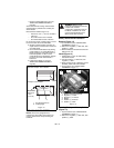
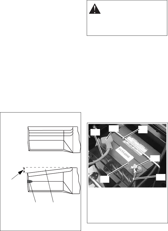
Discard mower blade if (figure 13):
• more than 1/2 in. (1.27 cm) of metal is
removed.
• the air lift erosion area is eroded.
• the mower blade is bent or broken.
Do not change angle of cutting edge or round
the corner at the end of mower blade.
2. Sharpen mower blade by removing an
equal amount of material from each end
of mower blade.
3. Check mower blade balance by sliding
mower blade on an unthreaded bolt. If
blade is balanced, it should remain in a
horizontal position. If either end of
mower blade moves downward, sharpen
the heavy end until mower blade is
balanced.
4. Install mower blade on unit (see
REPLACING MOWER BLADE on
page 20).
SERVICING THE BATTERY
NOTE: Unit comes equipped with a
maintenance-free battery that requires no
regular maintenance except cleaning the
terminals.
Battery Removal and Installation
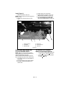
Remove (Figure 13)
1. Tip seat forward (see TIPPING SEAT
FORWARD on page 17).
2. Disconnect negative (–) cable first, then
positive (+) cable.
3. Remove battery hold-down bracket and
battery from unit.
Install (Figure 13)
1. Install battery on the unit with battery
hold-down bracket.
2. Connect positive (+) cable first, then
negative (–) cable.
3. Apply petroleum jelly or dielectric grease
to battery cable ends and terminals.
4. Tip seat back (see TIPPING SEAT
FORWARD on page 17).
Cleaning Battery and Battery Cables
(Figure 13)
1. Tip seat forward (see TIPPING SEAT
FORWARD on page 17).
2. Disconnect negative (–) cable first, then
positive (+) cable.
1. Air Lift Erosion Area
2. Cutting Edge
Figure 13
2
1
DO NOT Sharpen to this Pattern
Sharpen to this Pattern
DISCARD if
more than
1/2 in.
(1.27 cm)
WARNING: Battery posts,
terminals and related accessories
contain lead and lead
compounds, chemicals known to
the State of California to cause
cancer and reproductive harm.
Wash hands after handling.
1. Battery Hold-Down Bracket
2. Negative (–) Cable
3. Negative (–) Terminal
4. Battery
5. Positive (+) Terminal
6. Positive (+) cable
Figure 13
1
5
3
2
4
6


