9 - 41
Assemble in reverse order. Refer to Section 4.12 to
adjust friction wheel drive.
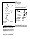
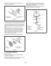
On models with plastic friction wheel hub, remove drive
cover nut and remove drive cover. Remove two taptites
and snap ring from gear cover and remove gear cover.
Remove cotter pin from shift link and move shift link out
of way.
Remove three #12-24 x 1/2" taptites from retainer
plate. Remove 3/16 x 7/8" roll pin from hex shaft with
roll pin driver. Slide hex shaft to left. Slide friction
wheel, retainer plate and thrust plate off hex shaft.
Remove taptites from thrust plate, separate thrust
plate, and remove friction wheel.
Install new friction wheel using reverse procedure.
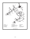
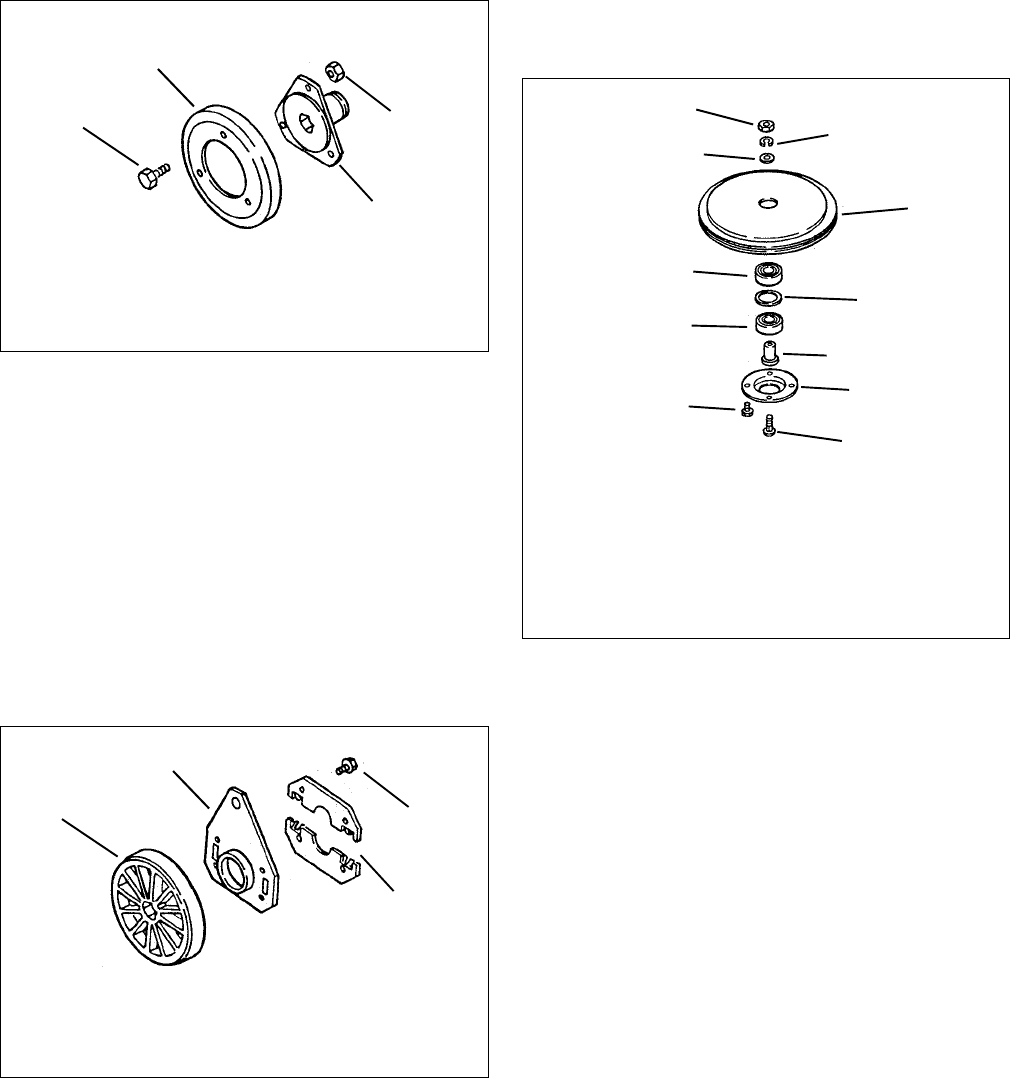
9.7 DRIVE DISK REMOVAL
Remove drive belt.
Remove nut, lockwasher and flat washer securing
drive disk to mower pan.
Remove four taptites securing bearing retainer to drive
disk, remove bearing retainer and spindle.
Press out bearings from drive disk using Ariens
Bearing Driver P/N 000026. Replace bearings with
Bearing Driver P/N 000046.
Inspect parts for wear or damage and replace as
necessary. Assemble in reverse order.
Figure 28
1. Cap Screw
2. Friction Wheel
3. Friction Wheel Hub
4. Lock Nut
1
2
3
4
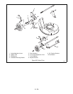
Figure 29
1. Taptite
2. Thrust Plate
3. Guide Plate
4. Friction Wheel
1
2
3
4
Figure 30
1. Nut
2. Lock Washer
3. Washer
4. Drive Disk
5. Ball Bearing
6. Washer
7. Spindle
8. Bearing Retainer
9. Taptite
10.Carriage Bolt
1
2
4
5
6
7
9
10
3
8
5


