9 - 40
9.1 INTRODUCTION
NOTE:
Rear wheels must be removed to perform
repairs in this section. Block up rear of mower to raise
rear wheels off work surface. Remove snap ring secur-
ing wheel to axle and remove washer and wheel.
9.2 GEAR REMOVAL
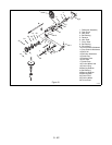
Remove snap ring securing gear cover over idler shaft,
remove taptites securing cover to drive mount, and
remove gear cover.
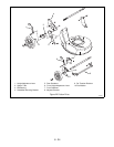
Slide differential assembly off axle and remove idler
gear from idler shaft.
Drive out roll pin securing pinion gear on hex shaft and
remove pinion gear.
Inspect parts for wear and or damage, replace as
necessary. Assemble in reverse order and grease
spline area.
9.3 AXLE REMOVAL
Remove snap ring next to axle spline on left side of
axle and remove axle bearing.
Remove cotter pin securing left side of rear protective
guard to bracket and move guard out of the way.
With snap ring pliers, spread snap ring apart on right
side of axle. Pull right wheel and axle from mower until
left end of axle clears drive mount.
Inspect parts for wear and or damage, replace as
necessary and assemble in reverse order being sure to
grease spline area.
9.4 DRIVE MOUNT REMOVAL
Remove axle and gears. Refer to Axle Removal and
Gear Removal Sections.
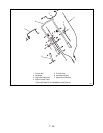
Remove extension spring from drive actuator. Loosen
nuts securing drive cable to drive actuator. Remove
drive cable spring from bracket on mower pan and
remove drive cable from drive actuator.
Remove cotter pin and washer from shift link. Remove
shift link, and drive mount.
Assemble in reverse order.
9.5 DRIVE MOUNT DISASSEMBLY
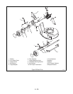
Drive out roll pin in hex shaft and remove hex shaft.
Press out bearings from drive mount with bearing
driver.
Remove taptites securing retainer plate to drive mount
and remove guide shaft.
Push idler shaft out of drive mount, inspect parts for
wear or damage and replace as necessary. Assemble
in reverse order.
9.6 FRICTION WHEEL REPLACEMENT
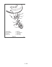
If rubber tire on friction wheel becomes worn, chipped,
or broken, friction wheel must be replaced.
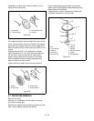
On models with steel friction wheel hub and 3 retaining
screws, remove the three cap screws and nuts that
secure friction wheel to hub (hole in bearing plate
provides access to hardware) and remove friction
wheel.
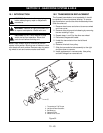
WARNING:
Remove wire from spark plug
before attempting any repair or adjustment
procedures.
WARNING:
Gasoline is highly flammable and
its vapors are explosive. Handle with care.
CAUTION:
DO NOT touch engine or parts
which are hot from operation. Allow such
parts to cool before servicing unit.
SECTION 9 - FRICTION DRIVE SYSTEM & AXLE
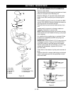
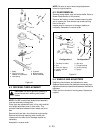
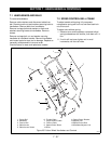
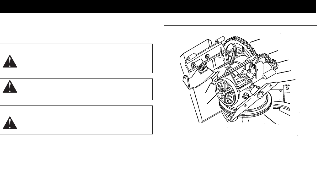
Figure 27
1. Differential
2. Idler Gear
3. Pinion Gear
4. Drive Carrier
5. Pivot Channel
6. Drive Disk
7. Friction Wheel
8. Shift Link
1
2
3
4
5
6
7
8


