


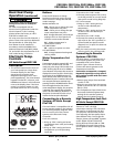
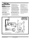
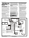
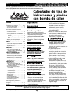
Figure 2 -
Recommended installation layout
POOL
HEATER
UNIONS
FILTER
POOL
PUMP
CHLORONATOR
WARM
WATER OUT
TO POOL
COLD WATER
IN FROM POOL
IN
OUT
CHECK
VALVE
THE UNIT MUST BE TRANSPORTED
IN THE UP-RIGHT POSITION AT ALL
TIMES AND MUST NOT BE DROPPED
OR TAILGATED. DAMAGE TO THE
UNIT DURING TRANSPORTATION IS
NOT THE RESPONSIBILITY OF THE
MANUFACTURER.
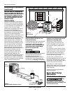
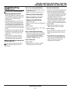
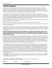
Unit Location
Once the unit has been inspected and
cleared of any transportation damage,
it is now time to locate the pool heater.
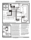
It is very important to understand the
location of the unit for the best
performance of operation. See Figure 1
for location recommendations. A
minimum of 18" of clearance between
the evaporator coils and shrubs, fences,
walls, etc. must be maintained for
adequate air intake. A minimum of 5' of
vertical clearance between the top of
the unit and any roof overhang or other
obstructions must be maintained in
order to prevent the re-circulation of
cold air back into the evaporator coils.
This is to maintain the efficiency of the
unit. A minimum of 36" of clearance
between the front of the unit (access
panel area) and any obstruction must
be maintained to allow maintenance on
the unit when necessary. The unit
should be located on a solid level
surface, a minimum of 36"x 36" for
proper drainage. Make sure any
sprinkler heads are not directly spraying
water on the unit. While heat pumps
are made for an outdoor environment,
they are not designed to have sprinkler
water constantly spraying them.
NOTE: This type of constant
watering directly on the unit can
void your warranty.
Condensation drain holes are provided
in all units for adequate removal of
condensation and rainwater. ALL
UNITS WILL HAVE CONDENSATION.
THIS SHOULD NOT BE MISTAKEN
FOR A LEAK IN THE UNIT.
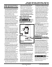
Plumbing
Where freezing weather is encountered,
the detachable connection/union
(provided) must be installed
immediately adjacent to the heater to
facilitate servicing and draining of the
heat exchanger. Draining is necessary
Phone: (877)-278-2797
2
Operating Instructions
to prevent damage to the
condenser shell and coil due to the
expansion of freezing water.
The minimum water circulation
capacity flowing through the pool
heater is 25 gallons per minute and
the maximum capacity is 80 gallons
per minute.
Do not install a water shutoff valve in
the piping from the outlet of the pool
heater to the pool or tub. However, a
check valve that does not include a
shut-off feature may be installed for
convenience during servicing.
A check valve or Hartford Loop is
recommended between the unit and a
chlorinator. The chlorinator must be
downstream of the heat pump. Failure
to do so may void the warranty.
If you have an in-floor cleaning
system, please take note of any special
plumbing requirements to operate all
units effectively.
Figure 2 shows the recommended
installation layout.
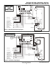
Basic Heat Pump
Operation
Electrical Connections
All
wiring
and electrical connections must be
performed by a qualified electrician.
Installations must be in accordance with
local and national codes.
www.aquaprosystems.com
5 feet
(minimum)
18“ min
18“ min
18“ min
36” clearance
5' Minimum
18" Min.
18"
Min.
36"Min.
18"
Min.
Figure 1 -
Unit Location
Installation Procedures
(continued)