


752864-100 Rev. C
All wiring must be performed by a licensed electrician in accordance with the national electrical code and all other
applicable codes.
WARNING:
When using electrical products, basic precautions should always be observed, including the following:
1. DANGER: RISK OF ELECTRIC SHOCK
Connect only to a circuit protected by a ground-fault circuit interrupter.
2. Grounding is required. The unit should be installed by a licensed electrician and grounded.
3. Install to permit access for servicing.
4. All building materials and wiring should be routed away from the pump body and heater (if equipped).
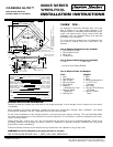
The whirlpool should be installed on a 120 vac, 20 amp dedicated circuit. The circuit should be hard-wired from the
electrical power supply panel. The circuit must be a three (3) wire circuit from the electrical supply panel. A grounded
neutral wire and a third wire, earth ground, are essential.
(4)
E-Z INSTALL WHIRLPOOL HEATER
ELECTRICAL INSTALLATION
INSTRUCTIONS
Install a separate 120VAC / 15AMP dedicated circuit with GFCI
(Ground Fault Circuit Interrupter) protection. With a No. 8 solid copper
wire, bond the heater to the homes electrical panel or approved local
bonding point. A bonding lug has been provided on the heater.
At initial start-up with power ON, push the GFCI test button. The
reset button should pop out. Push this button in to reset. If the GFCI
fails to operate in this manner, there is a ground fault or malfunction,
indicating the possibility of electrical shock. Turn off the power and
do not use the bath until the source of the problem has been
identified and corrected.
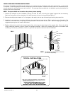
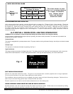
1. Route two separate branch circuits (figure 1) to the junction
box near the whirlpool. *Each branch circuit MUST BE
GFCI PROTECTED.
2. Use copper conductors only.
3. Insure the heater and pump are properly GROUNDED and
BONDED as required. Bonding connectors suitable for No.
8 AWG copper wire are located on both the pump and
heater assemblies.
a. Using No. 8 AWG copper wire, bond each of these
assemblies together to the homes electrical panel or
approved local bonding point.
Fig. 1
ELECTRICAL DIAGRAM
READ AND FOLLOW ALL INSTRUCTIONS
BLACK
WHITE
120 VAC
GND.
SEPARATE 20 AMP GFCI OUTLET
for2.1 H.P. PUMP
PUMP/MOTOR
ELECTRICAL INSTALLATION
HEATER
HEATER ON
R
ES
ET
OVERHEAT
PR
OTEC
TION
BLACK
WHITE
120 VAC
GND.
SEPARATE
15 AMP GFCI OUTLET
E-Z INSTALL
WHIRLPOOL
H
E
A
T
E
R
WHIRLPOOL ELECTRICAL INSTALLATION INSTRUCTIONS