


5
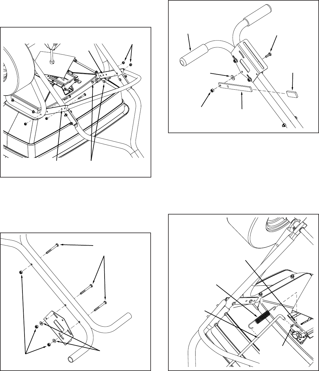
FIGURE 4
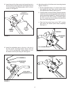
8. Attach the two upper handles together with
the flow control bracket as shown using three
1/4 x 2-1/2 in. bolts and nylock nuts. Do not tighten
two bolts in ow control bracket. Tighten third bolt in
upper handles. See gure 5.
45_0382Fig4
1/4-20 x 1-1/2 in.
HEX BOLT (B)
1/4-20 NYLOCK
NUT (E)
USE
MIDDLE
HOLE
USE THIS
HOLE
FIGURE 5
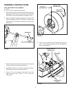
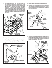
7. For the standard setup, use the holes shown in
the illustration. Other hole combinations allow
different handle heights and hopper angles. Do
not use holes in stand that are farthest apart as a
combination - ow gate may not close completely.
Attach the stand to the hopper frame tube using two
1/4 x 1-1/2 in. bolts and nylock nuts. Attach the stand
to the lower handle using two 1/4 x 1-1/2 in. bolts and
nylock nuts. Tighten all four bolts to secure the stand.
See gure 4.
45_0382Fig5
1/4-20 x 2-1/2 in.
HEX BOLT (A)
1/4-20 NYLOCK
NUT (E)
1/4 in. WASHER (F)
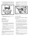
11. Attach the spring to the stainless steel pattern plate as
shown. Attach the opposite end of the spring to the 1/8
in. hole in the ow control rod. Rotate the end of the rod
into the ow control link. See gure 7.
45_0382Fig7
SPRING (L)
1/8 in. HOLE
SPRING
ANCHOR
HOLE
FLOW
CONTROL
LINK
FIGURE 7
45_0382Fig6
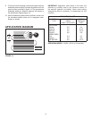
LEVER
LEVER
GRIP (Q)
1/4-20 NYLOCK
NUT (E)
1/4 in. NYLON
WASHER (G)
1/4-20 x 3/4 in.
HEX BOLT (C)
HANDLE
GRIP (P)
FIGURE 6
9. Install a handle grip on each handle. See gure 6.
10. Attach the ow control lever to the bracket using one
1/4 x 3/4 in. bolt, nylon washer and nylock nut. Tighten
carefully to allow the lever to move freely. Install the
vinyl grip. See gure 6.