4
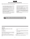
ASSEMBLY INSTRUCTIONS
TOOLS REQUIRED FOR ASSEMBLY
(1) Pliers
(2) 7/16"Wrenches
(2) 1/2"Wrenches
(2) 9/16"Wrenches
REMOVAL OF PARTS FROM CARTON
Removeallpartsandhardwarepackagesfromthecarton.
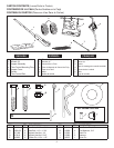
Lay out all parts and hardware and identify using the
illustrations on page 2.
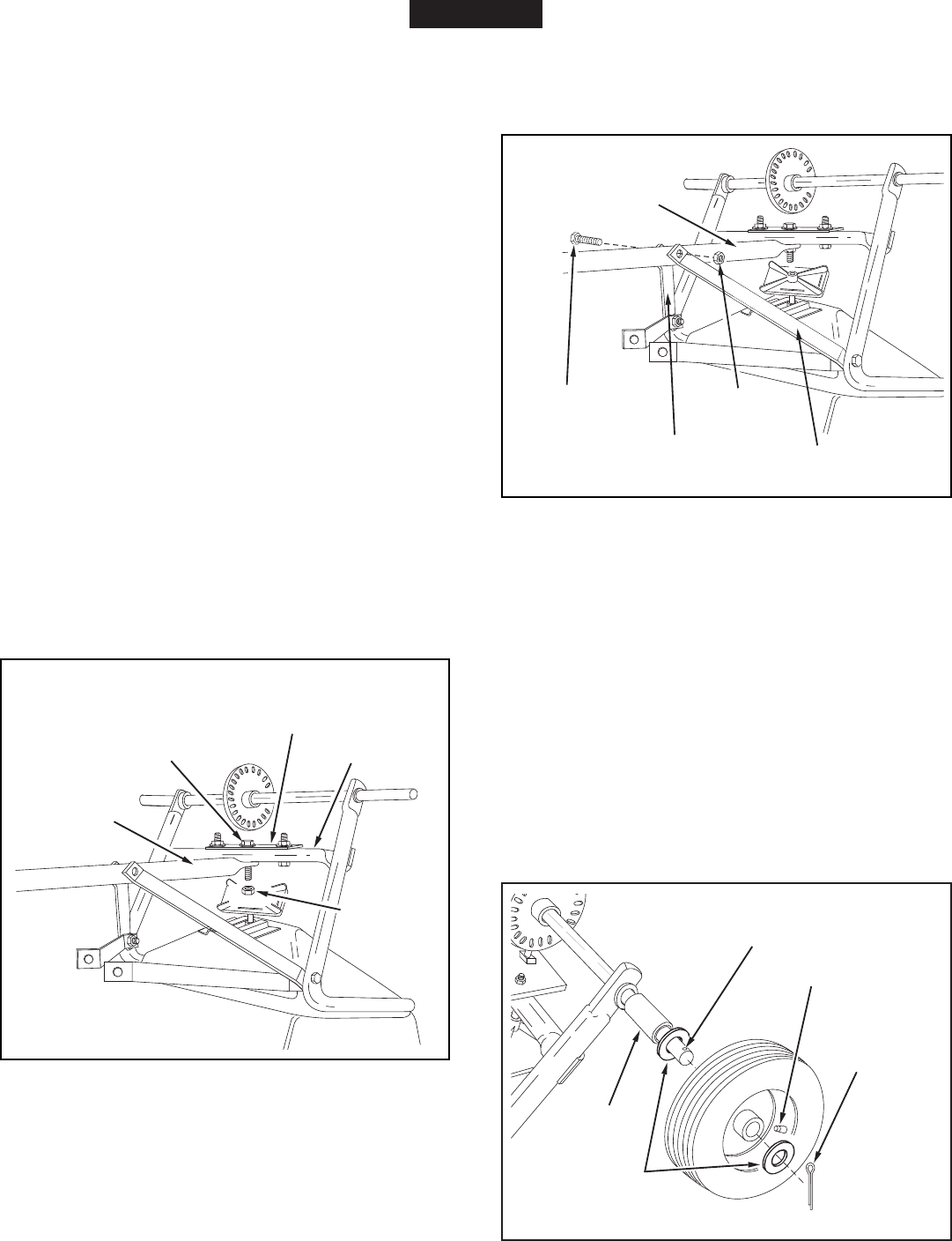
FIGURE 1
FIGURE 2
FIGURE 3
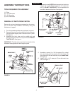
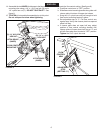
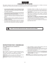
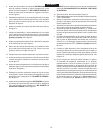
4. AssemblethetwoOUTERhitchbracestothehitchtube
usinga1/4"x1-3/4"(B)hexboltanda1/4"nylockhex
nut (C). DO NOT TIGHTEN YET.Donotassemblethe
innerhitchbracesatthistime.Seegure2.
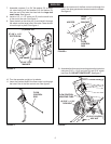
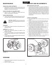
1. Turnthespreaderupsidedownasshowningure1.
2. Removethelocknutfromthemiddleboltinthecrossover
tubeandshaftsupportplate.Leavetheboltinplace.
Seegure1.
3. Assemble the hitch tube onto the middle bolt and
secureitwiththesamelocknutyouremoved.DO NOT
TIGHTEN YET.Seegure1.
IMPORTANT:Thehitchtubemustattachtothesideofthe
crossovertubeoppositetheshaftsupportplate.
CROSSOVER
TUBE
HITCH
TUBE
SHAFT
SUPPORT
PLATE
MIDDLE
LOCK NUT
MIDDLE BOLT
(B) 1/4" x 1-3/4"
HEX BOLT
(C) 1/4" NYLOCK
HEX NUT
HITCH BRACE
OUTER
HITCH
TUBE
HITCH BRACE
OUTER
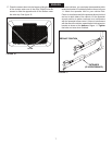
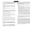
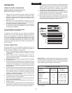
5. Assembleaspacer(I),a3/4"atwasher(G),awheel
(airvalvefacingout)andanother3/4"atwasher(G)
ontotheendoftheaxlethathasonlythesmall hole.
Seegure3.
6. Installa1/8"x1-1/2"cotterpin(E)intotheholeinthe
axle.Seegure3.
SMALL HOLE
(I) SPACER
(G) 3/4" FLAT
WASHER
(E) 1/8" x 1-1/2"
COTTER PIN
AIR VALVE
ENGLISH


