


5
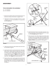
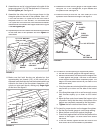
8. Assemble one end of a tongue brace to the side of the
tongue using two 1/4" x 5/8" hex bolts and 1/4" hex nuts.
Do not tighten yet.
See fi gure 4.
9. Assemble the other end of the tongue brace to the
triangular plate on the end of the spreader. Use a 1/4"
x 5/8" hex bolt and 1/4" nylock nut in the front hole of
the plate. Use a 1/4" x 3/4" hex bolt, 1/4" fl at washer and
1/4" nylock nut in the rear hole, with the bolt and washer
assembled on the inside of the hopper as shown in fi gure
4.
Do not tighten yet.
10. Repeat steps 8 and 9 to attach the second tongue brace
to the other end of the spreader and then
tighten
all
loose bolts.
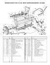
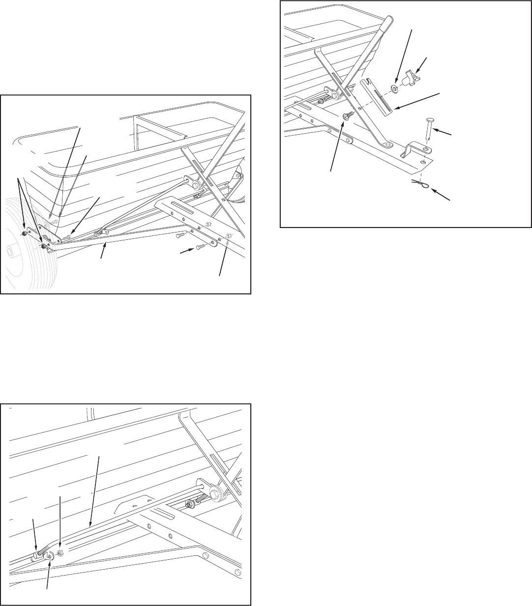
1/4" NYLOCK NUT
BRACKET
FERRULE
FLOW CONTROL ROD
FIGURE 5
11. Make sure that both ferrules are adjusted so that
approximately ten threads (1/2") of the control rod is
exposed. Insert both ferrules into the brackets which are
riveted to the front of the fl ow plates. Assemble a 1/4"
nylock nut onto each ferrule, making only
fi nger tight
at this time. See fi gure 5.
1/4" x 5/8"
HEX BOLT
1/4" FLAT WASHER
(One per side)
1/4" NYLOCK NUT
TONGUE
BRACE
1/4" x 3/4"
HEX BOLT
1/4"
NYLOCK
NUT
1/4" x 5/8"
HEX BOLT
FIGURE 4
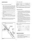
12. Assemble the fl ow control gauge to the hopper brace
using the 1/4" x 3/4" carriage bolt, a nylon washer and
the plastic knob. See fi gure 6.
13. Install the hitch pin and the 1/8" hair cotter pin in the
spreader hitch bracket and tongue. See fi gure 6.
PLASTIC
KNOB
NYLON
WASHER
1/4" x 3/4"
CARRIAGE BOLT
FLOW
CONTROL
GAUGE
1/8" HAIR
COTTER PIN
3/8" HITCH PIN
FIGURE 6
14. To check for correct opening of hopper fl ow plates:
a. Set the fl ow control gauge at the highest setting.
b. Move the fl ow control arm away from the hopper until
it rests against the gauge. The slots in the bottom
of the hopper should now be completely open. The
edge of the fl ow plates should be just clear of the
ends all the slots.
c. If the fl ow plates are not straight with the slots, screw
one ferrule up or down on one side of the control
rod.
d. If the fl ow plates open to far or not far enough, screw
both ferrules equally up or down on the control
rod.
d. Move the fl ow control arm toward the hopper to the
off position. Verify that the slots in the bottom of the
hopper are completely covered by the fl ow plates.
e.
Tighten
the lock nuts and then loosen 1/4 turn.
15. To check for proper tension on the hopper fl ow plates:
a. Set the
fl ow control gauge at a mid range setting.
b. Move the fl ow control arm against the gauge.
c. Press fi rmly against the front of the fl ow plates at the
bottom of the hopper. The fl ow control arm should
not move.
d. If the arm moves, tighten the hex lock nuts on the
fl ow control arm until movement is prevented.