


4
TOOLS REQUIRED FOR ASSEMBLY
(2) 7/16" Wrenches
(2) 9/16" Wrenches
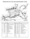
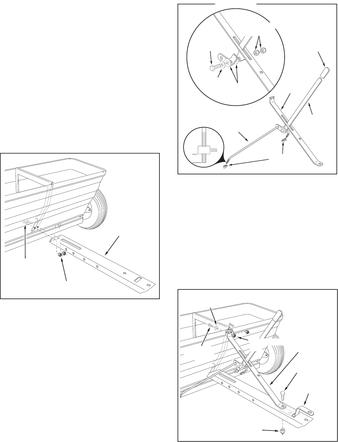
FIGURE 3
ASSEMBLY
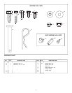
NYLON
WASHER
1/4" FLAT
WASHER
1/4" x 1-1/4"
HEX BOLT
PLASTIC
GRIP
FERRULE
FLOW
CONTROL
ROD
FLOW
CONTROL
ARM
HOPPER
BRACE
1/2"
1/4" NYLOCK
NUTS
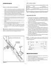
FIGURE 2
3. Assemble the plastic grip onto the end of the fl ow control
arm as shown in fi gure 2.
4. Insert the fl ow control arm through the slot in the hopper
brace. Place a nylon washer on each side of the arm
and attach it to the brace's welded bracket using a 1/4"
x 1-1/4" hex bolt, a 1/4" fl at washer and two 1/4" nylock
nuts as shown in fi gure 2.
Tighten
the fi rst nylock nut
until there is noticeable resistance when moving the fl ow
control arm, then
tighten
the second nylock nut.
5. Place the fl ow control rod through the hole at the end
of the fl ow control arm. Assemble the two ferrules onto
the threaded ends of the rod so that approximately 10
threads (1/2") of the rod extends through the ferrules.
See fi gure 2.
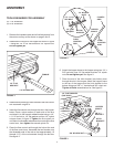
1/4" NYLOCK NUT
1/4" x 5/8"
HEX BOLT
TONGUE
FIGURE 1
1. Remove the hardware pack and all individual parts from
the carton and lay out as shown on page 2 and 3.
2. Assemble the tongue to the hopper as shown in fi gure
1 using two 1/4" x 5/8" hex bolts and 1/4" nylock nuts.
Do not tighten yet.
3/8" NYLOCK NUT
1/4" x 5/8"
HEX BOLT
3/8" x 1"
HEX BOLT
1/4" FLAT WASHER
(ONE ONLY)
HOPPER
BRACE
HITCH
BRACKET
1/4" NYLOCK
NUT
6. Attach the hopper brace to the hopper using two 1/4" x
5/8" hex bolts, one 1/4" fl at washer and two 1/4" nylock
nuts.
Do not tighten yet.
See fi gure 3.
7. Place the end of the hitch bracket (two holes) down
through the slot in the tongue. Attach the hopper brace
to the top of the tongue and the hitch bracket to the
bottom using one 3/8" x 1" hex bolt and 3/8" nylock nut.
Tighten all bolts
assembled so far. See fi gure 3.