


5
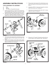
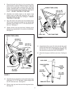
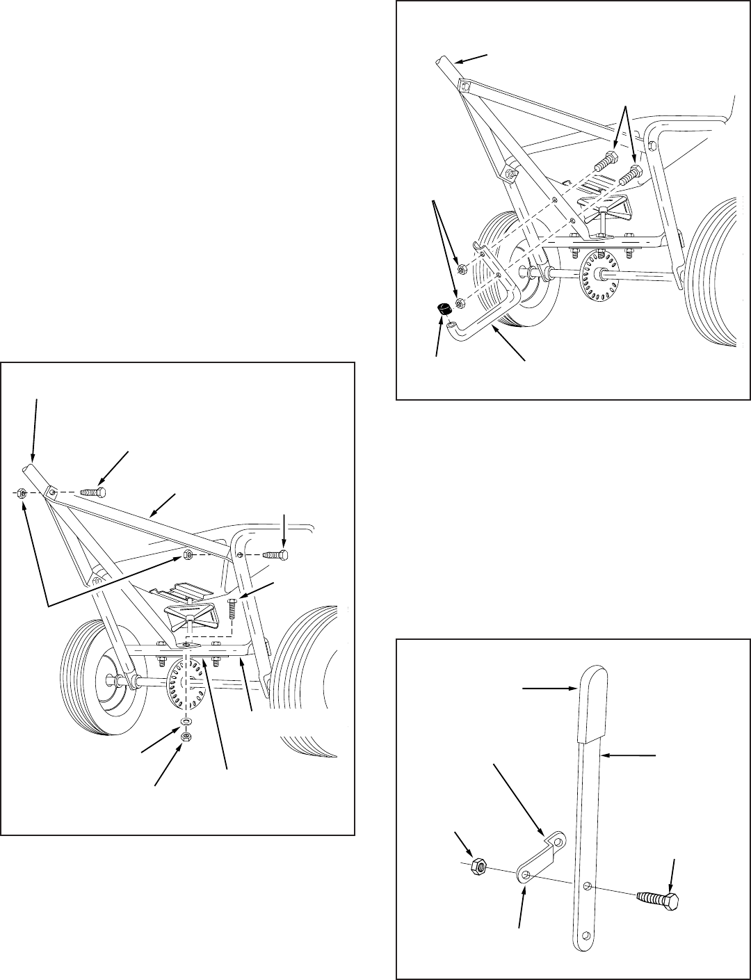
9. Place the handle tube (long) on the crossover tube,
(side between crossover tube and hopper), align the
holes in the handle tube, crossover tube, and shaft
support. Assemble with 1/4" hex bolt, flat washer and
hex lock nut removed in the previous step. See figures
6 and 7. DO NOT TIGHTEN AT THIS TIME.
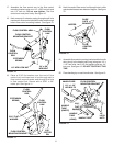
10. Assemble two handle braces to the inside of the
hopper frame, one each side, using two 1/4" x 1-1/2"
hex bolts and two 1/4" lock nuts. See figure 7. DO NOT
TIGHTEN AT THIS TIME.
11. Align the holes in the ends of the two handle braces
with the hole nearest the middle of the handle tube
assembly. Secure with a 1/4" x 1-1/2" hex bolt and 1/4"
lock nut. See figure 7.
12. Tighten all hex lock nuts and bolts, following same
sequence as assembled in the previous three steps.
See figure 7.
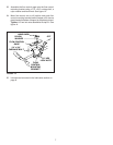
FIGURE 9
13. Assemble the leg stand tube to the handle tube (long)
using two 1/4" x 1-1/2" hex bolts. Secure tightly with
two 1/4" hex lock nuts. See figure 8.
14. Place a vinyl cap over the end of the leg stand tube.
See figure 8.
FIGURE 7
FIGURE 8
15. Assemble the flow control link (the end with the small
hole) to the flow control arm using one 1/4" x 5/8" hex
bolt and one 1/4" lock nut. Do not over tighten. The
flow control link must pivot freely. See figure 9.
16. Place the vinyl grip on the flow control arm. See figure
9.
1/4" HEX
BOLT
1/4" HEX
LOCKNUT
FLAT WASHER
HANDLE TUBE (LONG)
HEX BOLT
1/4" x 1-1/2"
HEX BOLT
1/4" x 1-1/2"
HITCH
BRACE
1/4"
LOCK
NUT
CROSSOVER
TUBE
SHAFT SUPPORT
HANDLE TUBE (LONG)
1/4" x 1-1/2"
HEX BOLTS
1/4"
LOCK
NUT
VINYL CAP
LEG STAND TUBE
FLOW CONTROL
LINK
VINYL GRIP
FLOW
CONTROL
ARM
1/4" x 5/8"
HEX BOLT
SMALLEST HOLE
1/4" HEX
LOCK NUT