


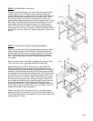
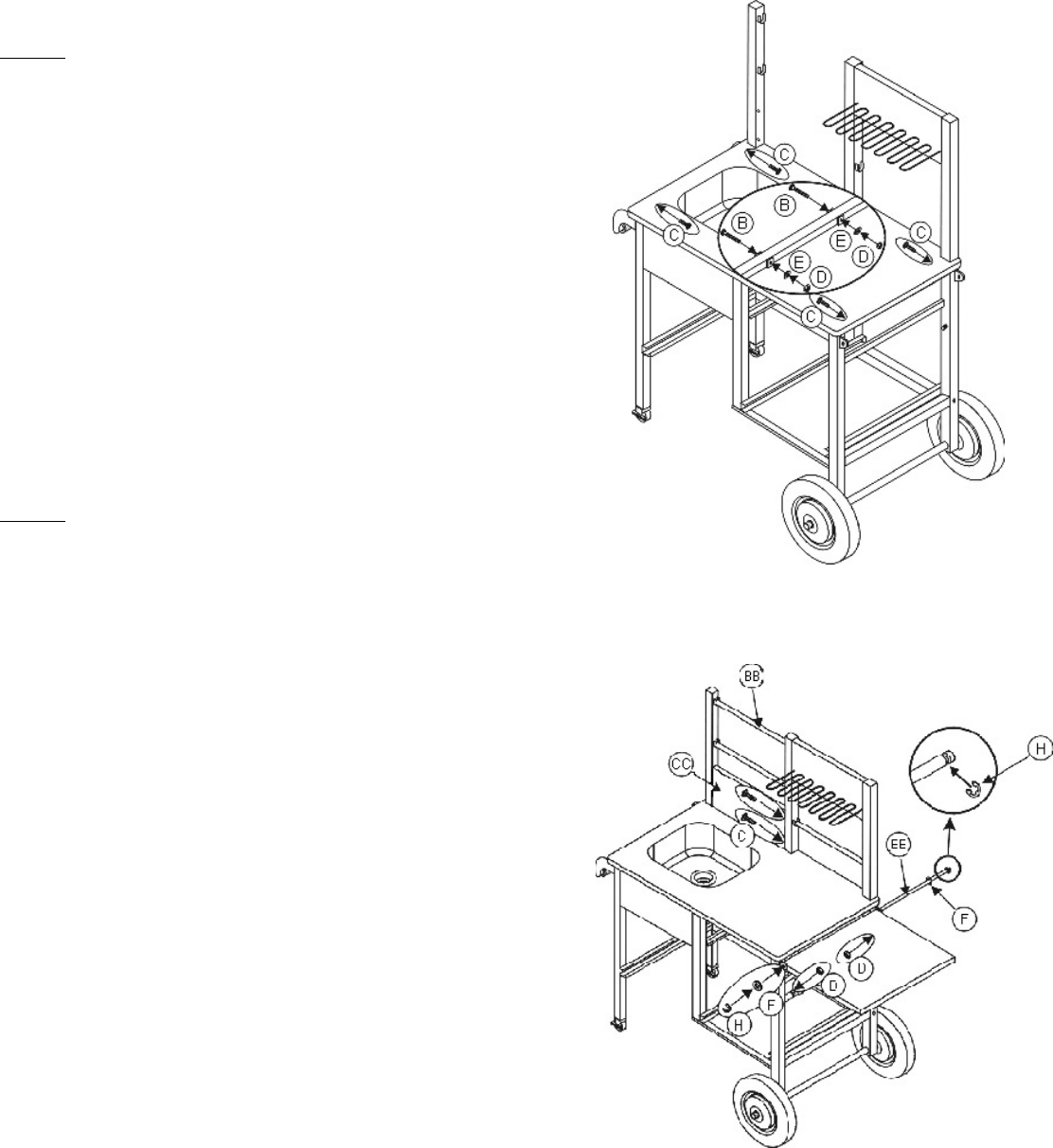
STEP 6 SINK ASSEMBLY (continued)
Position the sink top assembly (Z) over the left side, right side and
middle support frames, making sure the holes for the bolts are
properly aligned. Once in proper position, use M6 x 16mm bolts (C)
to attach sink top/basin assembly to the left support frame. Insert
bolts through holes in sink top into the fixed nuts in the left side
support frame. Repeat procedure for right side support frame. Insert
M6 x 50mm bolts (B) through the holes in the middle portion of the
sink top/basin assembly through the holes in the middle support
frame. Be sure to insert the bolts in the direction towards the right
side support frame as shown in figure 6. Add a 6mm washer (E) and
an m6 nut to the end of each bolt. Tighten with wrench. Do not over
tighten.
Figure 6
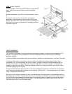
Figure 7
STEP 7 FAUCET AND FOLDING COUNTER ASSEMBLY
Attach rear faucet panel (CC) to left side support frame and middle
support frame using M6 x 16mm bolts (C). Insert bolts outwards
through holes from behind the rear faucet panel and into the fixed
nuts in the middle support frame. Repeat procedure for opposite
side. Tighten bolts using hex wrench. Tighten completely. Do not
over tighten.
Attach the three dowels rods (BB) by snapping into place as shown.
Two on left side, one on right side beneath the coiled shelf.
Attach folding counter (DD) to right side of the assembled unit.
Position the folding counter between the axle guides on the right
side support frame (just below where it meets with the sink top/basin
assembly). Slide the folding shelf axle (EE) through the axle guides
and through the hollow shaft of the folding shelf. Add 10mm washer
to each end of the axle. Secure into place by attaching 10mm end
clips (H) to each end of the axle. Attach lower part of front hinge to
the front right side support frame as shown in figure7. Attach one
end of hinge to threaded post on right side frame and the other end
of hinge to threaded post on the underside of the folding shelf.
Secure with M6 nut (D). Tighten with wrench. Repeat for remaining
hinge. Note: hinge will lock with shelf in the “up” position. Collar on
hinge will slide down to lock into position.
Attach faucet (II) to rear faucet panel (CC) by unscrewing plastic
gasket and sealer ring from faucet head. Place faucet through hole
in rear faucet panel and re-screw gasket and ring. Adjust faucet until
properly aligned. Tighten.
PAGE 3