QTY
DESCRIPTION ORDER PART #
QTY
DESCRIPTION ORDER PART #
QTY
DESCRIPTION ORDER PART #
M10 X 55MM BOLT
3
M6 X 50MM BOLT
6
M6 X 16MM BOLT
16
M6 NUT
12
6MM WASHER
6
10MM WASHER
5
12MM WASHER
4
10MM END CLIP
2
12MM END CLIP
4
10MM PVC COVER
2
12MM PVC COVER
2
M6 PVC NUT COVER
4
LARGE WHEEL
2
WHEEL COVER
4
AXLE SLEEVE
3
RIGHT SUPPORT
FRAME
1
LEFT SUPPORT
FRAME
1
CUSHION
HANDLE GRIP
1
CASTERS
2
FRONT SUPPORT
BAR
1
REAR SUPPORT
BAR
1
MIDDLE SUPPORT
FRAME
1
FRONT PANEL
1
COILED SHELF
1
DRAIN PLUG
1
DOWEL RODS
3
REAR FAUCET
PANEL
1
FOLDING
COUNTER
1
AXLE FOR
FOLDING COUNTER
1
DRAWER
1
BOTTOM TRAY
2
“S” HOOKS
6
FAUCET
1
FOLDING COUNTER
HINGE
2
STEP 1
identify all parts packed in carton against the parts list. Remove all protective materials. Place parts
on a non-arasive surface to avoid scratching. If you are missing any parts or are unsure how to
proceed with assembly, call our Customer Service Center at 1-800-416-3511 (Mon - Fri 9a-5p
EST). Do not attempt assembly if any parts are missing or damaged.
Read entire assembly instructions before beginning assembly.
A
F
E
D
C
B
K
J
I
H
G
M
L
N
S
R
Q
P
O
X
W
V
U
T
Z
Y
AA
FF
EE
DD
CC
BB
JJ
I I
HH
GG
WHEEL AXLE
1
SINK TOP BASIN
1
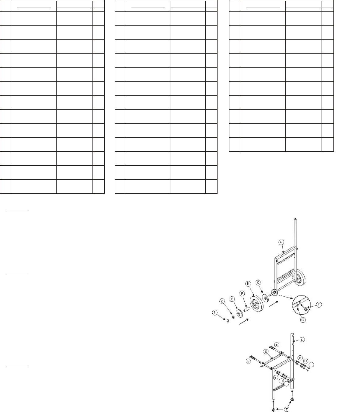
STEP 2 WHEEL ASSEMBLY
Insert wheel axle (M) through bottom shaft of right side support frame
(Q).so that it is centered inside the shaft with equal amount of axle on
each side. Snap 12mm end clip (I) on notch in axle closest to the right
side support frame (Q). Add the following parts to the axle in this order:
12mm washer (G), wheel cover (O), axle sleeve (P), wheel (N), wheel
cover (O), 12mm washer (Q), 12mm end clip (I) as shown in figure 1. Be
sure the wheel is inserted over the axle sleeve in a manner that allows it
to rotate freely. Secure the wheel assembly on the axle with the 12mm
washer clip (I). Repeat procedure for opposite side wheel.
STEP 3 LEFT SIDE SUPPORT FRAME ASSEMBLY
Screw in the two casters (T) into the bottom of the left side support frame (R) as
shown in figure 2. Add the cushion handle grip (S) to the left side support frame
(R) as shown in figure 2. Insert two M6 x 50mm bolts (B) through end of cushion
grip handle and through the holes in the left side support frame. Add a 6mm
washer (E), 6mm nut (D). Tighten with wrench. Do not over tighten. Add M6 PVC
cover to the end of each nut. Repeat on opposite side of cushion grip handle.
Figure 1
Figure 2
WB0001 WB0014
WB0013
WB0012
WB0011
WB0010
WB0009
WB0008
WB0007
WB0006
WB0005
WB0004
WB0003
WB0002
WB0023
WB0022
WB0021
WB0020
WB0019
WB0018
WB0017
WB0016
WB0015
WB0024
PAGE 1
TOOLS REQUIRED FOR ASSEMBLY
Hex Wrench
Hex Bolt Driver
MULTI-PURPOSE WORK BENCH ASSEMBLY INSTRUCTIONS
#92558


