


Agilent N518xA, E8663B, E44x8C, and E82x7D Signal Generators Programming Guide 311
Creating and Downloading User-Data Files
Pattern RAM (PRAM) Data Downloads (E4438C and E8267D)
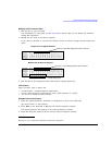
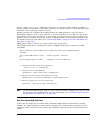
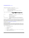
As seen in Table 8-5, only four bits, shown in the following list, can change state:
•bit 0—data
•bit 2—bursting
•bit 6—EVENT 1 rear panel output
• bit 7—pattern reset
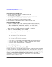
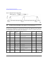
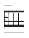
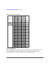
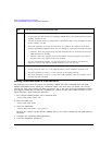
Because a PRAM byte has only four bits that can change states, there are only 15 possible byte
patterns as shown in Table 8-6. The table also shows the decimal value for each pattern, which is
needed for downloading data using the list format shown on page 314.
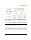
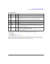
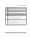
1 Reserved 0 Always 0
2 Burst 0/1 1 = RF on
0 = RF off
For non-bursted, non-TDMA systems, to have a continuous signal, set this bit to 1 for all
bytes. For framed data, set this bit to 1 for on timeslots and 0 for off timeslots.
3 Reserved 0 Always 0
4 Reserved 1 Always 1
5 Reserved 0 Always 0
6EVENT1
Output
0/1 To have the signal generator output a single pulse at the EVENT 1 connector, set this bit
to 1. Use this output for functions such as a triggering external hardware to indicate when
the data pattern begins and restarts, or creating a data-synchronous pulse train by
toggling this bit in alternate bytes.
7 Pattern Reset 0/1 0 = continue to next sequential memory address.
1 = end of memory and restart memory playback.
This bit is set to 0 for all bytes except the last byte of PRAM. To restart the pattern, set
the last byte of PRAM to 1.
Table 8-5 PRAM Data Byte
Bit Function Value Comments