4
Chapter 2 Hardware Installation
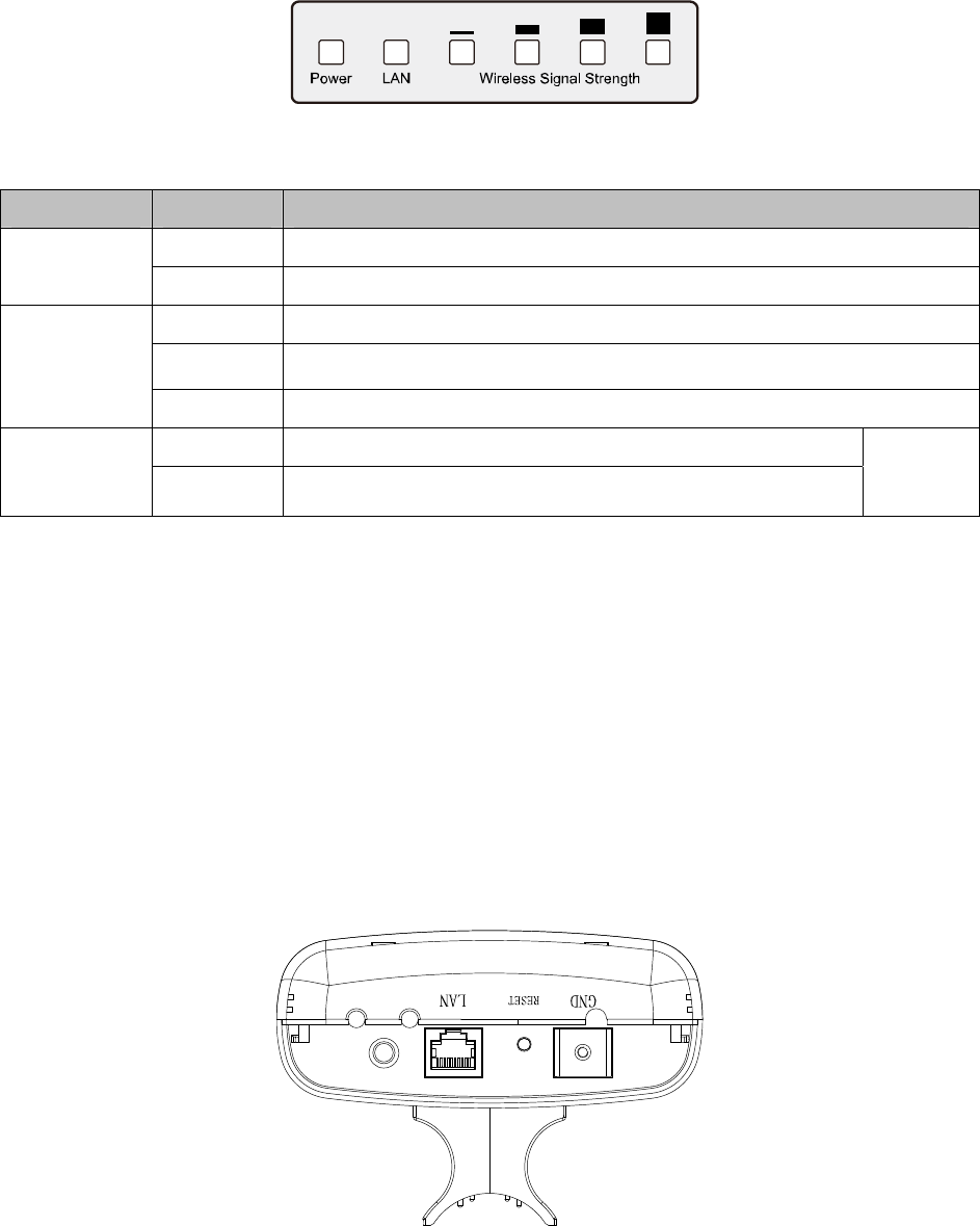
2.1 LED Explanation
TL-WA5210G consists of several LED indicators, which is designed to indicate connections and
wireless signal.
Figure 2-1 Front Panel sketch
View from left to right.
Name Status Indication
Off No Power
Power
On Power on
Off There is no device linked to the corresponding port
On There is a device linked to the corresponding port but no activity
LAN
Flashing There is an active device linked to the corresponding port
Off There is no remote wireless signal Wireless
Signal
Strength
On Indicates the wireless signal strength of a remote AP
Client or
Repeater
mode
Table 2-1
)
Note:
For Wireless Signal Strength LEDs:
¾ In AP or Bridge mode, all the four LEDs will light up.
¾ In Client or Repeater mode, the corresponding LED(s) will light up when the RSSI value
(wireless signal strength value) reaches the RSSI Threshold. The value of RSSI Threshold
can be set on Wireless Advanced Settings page as shown in Figure 4-26.
For example
, if the RSSI value is 30, the RSSI Threshold of the four LED are 15, 25, 35, 45
respectively, and then the LEDs whose RSSI Threshold are 15 and 25 will light up.
2.2 Interfaces and button
Figure 2-2 Rear Panel sketch
View from left to right, the parts are explained below.


