GVTP SM32-R0303.1
3
unit assembly (cont.)
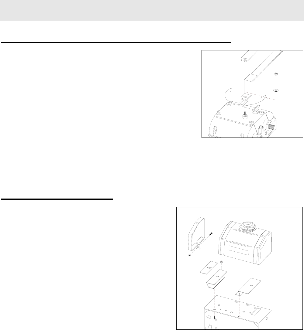
TRANSMISSION SHIFT LEVER ASSEMBLY (cont.)
• Position ‘double-D’ hole in bottom leg of shift
lever onto transmission stud, then slowly move
handle of shifter back and forth until hole drops
onto matching base of stud.
• Replace washer and nut onto transmission
stud. Tighten securely. Replace lock nut onto
1/2” bolt. Tighten snugly while allowing for
shifter movement.
• Work shift lever through gear range, adjusting
indicator panel for display alignment, then
tighten indicator panel hardware.
FUEL TANK ASSEMBLY
• Install fuel tank mount brackets (2:57, 58) onto
engine deck using four 5/16 x ¾” hex bolts and
serrated flange nuts (2:59-60). Do not tighten.
• Place rubber pads (2:61) on top of mount
brackets, making sure to not block fuel tank tab
slots.
• Place fuel tank (2:65) on top of slotted rubber
pads, making sure tabs on bottom of tank drop
through slots in tank brackets.
• Slip fuel tank straps (2:62) around ends of tank,
making sure bottom of straps slip under top
ends of mounting brackets. Secure each strap
with one 1/4-20 x 1-1/2” hex bolt and serrated
flange nut (2:63-64). Tighten both straps and
mounting bracket hardware securely.
• Slip end of fuel line from engine fully onto
barbed nipple of fuel elbow (located under
tank), securing with supplied spring clamp.


