MP875 Modem User Guide
60 2130808
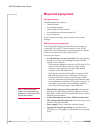
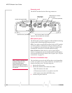
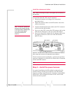
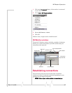
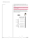
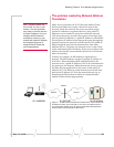
Digital output devices
Digitaloutputdevicesarethosethathaveonlytwostatesand
thestateiscontrolledbyasignalfromtheMPmodem.Any
devicethatistobeswitchedonandofffrom3GWatcher
wouldbeinstalledasadigitaloutputdevice.
Adigitaloutputcanbeconnectedtotwoofthepinsonthe
DB15HDconnector:Pins3and11.(Thesecanbeusedfor
eitherinputoroutput.)
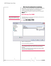
Note: Before using the input/output lines, you must configure them as
inputs or outputs.
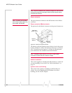
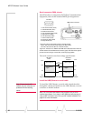
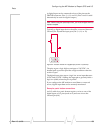
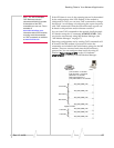
Typicallyadigitaloutputdeviceshouldbeconnectedbetween
Ground(pin10)andtheoutputport(Pin3or11).
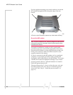
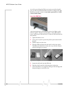
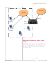
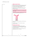
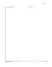
Figure 6-3: Wiring for using Pin 3 (digital output) as an electronic switch. Pin
10 is Ground.
ThedigitalI/Oportsprovideopen‐collectoroutputtoa
maximumof500
mA.
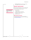
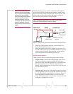
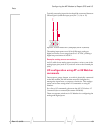
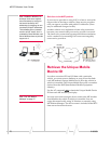
Analog input devices
Analoginputdevicesarethosethatgenerateasignalof
varyingvoltage,based onthe stateofan instrumentorgauge.
Anexampleofananaloginputdevicemightbeasensorthat
detectsthevehicle’sspeed.
Ananaloginputcanbeconnectedtofourofthepinsonthe
DB15HDconnector:Pins7,8,14,and15.