58 Rockwell Automation Publication 1412-UM001D-EN-P - September 2012
Chapter 4 DATAVIEW Software
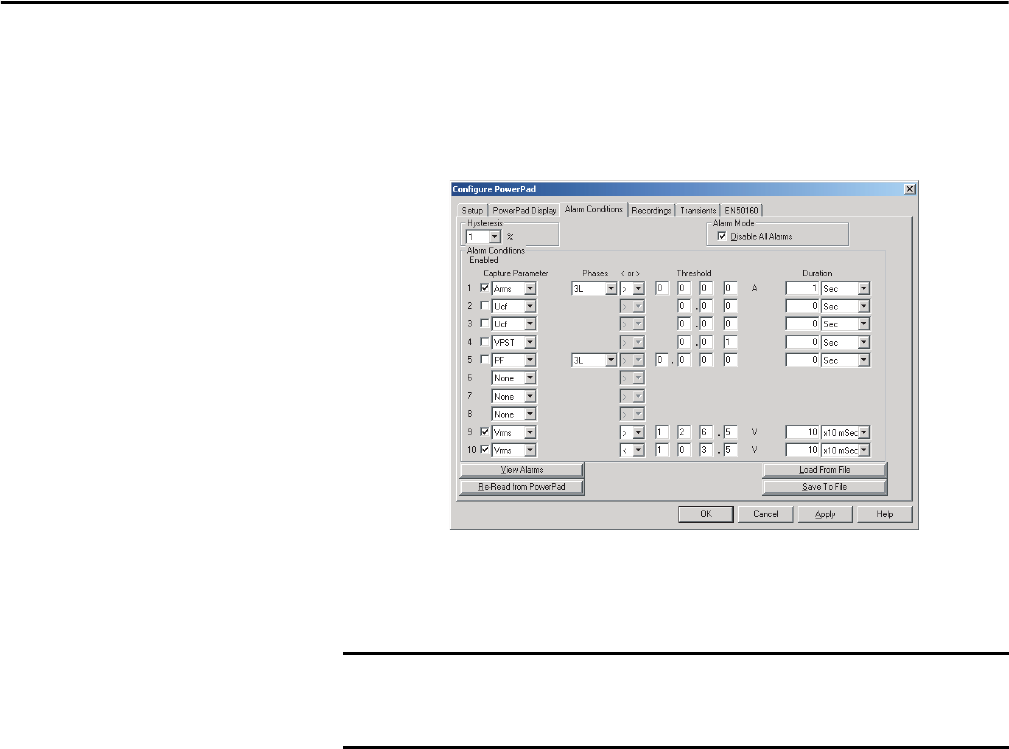
Alarm Conditions Configuration
The Alarm Conditions window lets you set up 10 alarm configurations.
Figure 6 - Alarm Conditions Window
• Hysteresis: This value for alarms is set to prevent multiple recordings of an
event that goes above the threshold and a certain percentage below it at
times.
• Disable All Alarms: When this box is checked, all alarms will be disabled
even if the individual alarm enable box is checked.
• Enabled: When check box is checked, alarm is enabled.
• Capture Parameter: The Alarm will be triggered based on the value of the
selected parameter.
Choices include:
– None: no alarm
– Vunb: voltage unbalance
– Vrms: voltage root mean squared
– Aunb: current unbalance
– Urms: voltage phase minus phase root mean squared
– Hz: frequency
– Akf: current K factor
– Arms: current root mean squared
– Vthd: voltage total harmonic distortion
– VPST: voltage short term flicker
– Uthd: voltage phase minus phase total harmonic distortion
– Vcf: voltage crest factor
– Ucf: voltage phase minus phase crest factor
Alarm threshold is 100V or higher, hysteresis is 1%. When the voltage goes up
to 100V, the alarm condition starts. When the voltage goes back down to 99V,
the alarm condition stops.


