4 Pelco Manual C1905M (10/99)
REAR
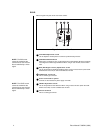
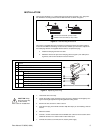
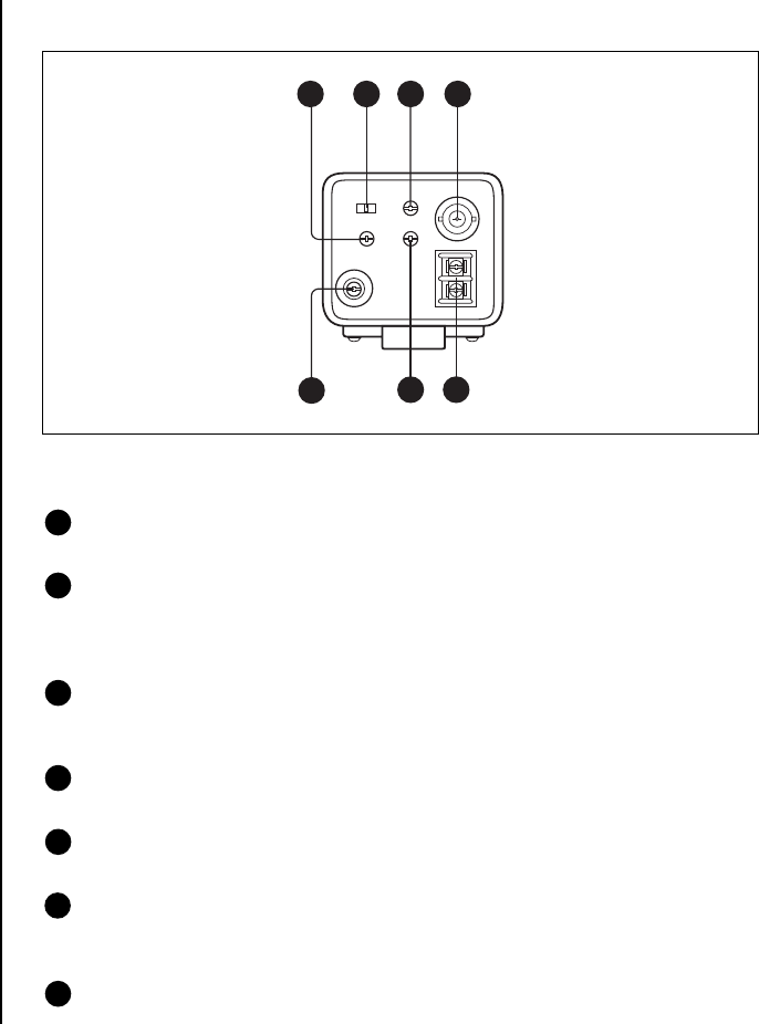
Refer to Figure 2 for parts on the rear of the camera.
Figure 2. Location of Rear Parts
6 V-PHASE adjustment screw
Use to adjust the vertical phase of cameras synchronized by line lock.
7 CCD-IRIS ON/OFF switch
When using a manual iris lens, set the switch ON to automatically adjust the sensitivity
according to the incident light conditions. When using an auto iris lens, set the switch
OFF.
8 BLC (Backlight Control) adjustment screw
Use to compensate for backlight conditions when using a manual iris lens (when CCD-
IRIS switch is set to ON) or a DC-controlled auto iris lens.
9 VIDEO OUT connector
This is a BNC-type connector.
10 Screw terminals for power
Connect an external Class 2 power supply of 24 VAC.
11 LEVEL adjustment screw
Use to compensate for the video level when using a manual iris lens (when the CCD-
IRIS is set to OFF) or a DC-controlled auto iris lens.
12 Ground terminal
This is a screw-type terminal.
7
VIDEO OUT
BLC
CCD-IRIS
ONOFF
V-PHASE
+-
LH
AV PK
LEVEL
GND
AC 24V
96 8
101112
NOTE:
The BLC screw
cannot be used when the
camera has an auto iris lens
that is controlled by a video
signal.
NOTE:
The LEVEL screw
cannot be used when the
camera has an auto iris lens
that is controlled by a video
signal.