[
4
]
Pelco Manual C1985M-E (4/03)
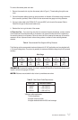
Power and Video Connections
The MC3651H-2 camera is designed to operate from a 12 VDC or 24 VAC power supply. The power sup-
ply connections are shown in Figure 1. The LED on the back panel of the camera indicates that power is
connected. Use only a Class 2 isolated power supply. Power consumption is less than five watts.
Figure 4. Power Supply Connections
24 VAC 12 VDC
CLASS 2
ISOLATED
POWER
SUPPLY
CLASS 2
ISOLATED
POWER
SUPPLY
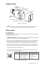
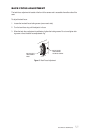
Camera Mounting
Use a standard 1/4-20 screw (provided) with a maximum thread length of 3/8-inch (10 mm) for top or bot-
tom camera mounting. The mount adapter may be fitted to the top or bottom of the camera. The camera
is shipped with the mount adapter located on the top of the camera.
To change the mount adapter position:
1 Remove the four screws from the mount adapter located on the top of the camera.
22
22
2 Remove the trim cover from the bottom of the camera by prying it loose. Place the trim cover on the
top of the camera where the mount adapter was removed. Press into place.
3 Install the mount adapter to the bottom of the camera. Secure with the four screws removed in step 1.
Figure 3. Camera Mounting
3
2
1