TN
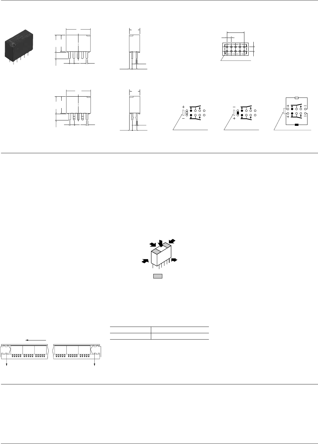
DIMENSIONS (Unit: mm inch)
NOTES
For Cautions for Use, see Relay Technical Information.
External dimensions
Standard PC board terminal
Self-clinching terminal
General tolerance: ±0.3 ±.012
3.5
.138
2.54 0.5
0.25
1.385
2.54
14
551
9.8
9.5
.386
.374
5.6
.100 .020
.010
.055
.100
.220
3.5
.138
2.54 0.5
0.25
1.385
2.54
14
551
9.8
9.5
.386
.374
5.6
.100 .020
.220
.010
.055
.100
PC board pattern (Bottom view)
2.54
10.16
2.54
10-1.0 dia. hole
10-.039 dia. hole
.100
.100
.400
Tolerance: ±0.1 ±.004
Schematic (Bottom view)
Single side stable
(Deenergized condition)
1-coil latching
(Reset condition)
2-coil latching
(Reset condition)
Direction indication
10 9 8 7 6
1 2 3 4 5
Direction indication
10 9 8 7 6
1 2 3 4 5
Direction indication
10 9 8 7 6
1 2 3 4 5
1. Coil operating power
Pure DC current should be applied to the
coil. The wave form should be
rectangular. If it includes ripple, the ripple
factor should be less than 5%.
However, check it with the actual circuit
since the characteristics may be slightly
different. The nominal operating voltage
should be applied to the coil for more
than 10 ms to set/reset the latching type
relay.
2. Coil connection
When connecting coils, refer to the wiring
diagram to prevent mis-operation or
malfunction.
3. External magnetic field
Since T series relays are highly sensitive
polarized relays, their characteristics will
be affected by a strong external magnetic
field. Avoid using the relay under that
condition.
4. Packing style
The relay is packed in a tube with the
relay orientation mark on the left side, as
shown in the figure below.
5. Automatic insertion
To maintain the internal function of the
relay, the chucking pressure should not
exceed the values below.
Chucking pressure in the direction A:
9.8 N {1 kgf} or less
Chucking pressure in the direction B:
9.8 N {1 kgf} or less
Chucking pressure in the direction C:
4.9 N {500gf} or less
Please chuck the portion.
Avoid chucking the center of the relay.
In addition, excessive chucking pressure
to the pinpoint of the relay should be
avoided.
6. Soldering
Preheat according to the following
conditions.
Soldering should be done at 260±5°C
500±41°F within 6 sec.
Stopper
(gray)
Orientation (indicates PIN No.1) stripe
Stopper
(green)
Temperature 120°C 248°F or less
Time Within 120 sec
A
C
B
All Rights Reserved © COPYRIGHT Matsushita Electric Works, Ltd.


