OPTIONAL EQUIPMENT CONNECTIONS
7 z
ENGLISH
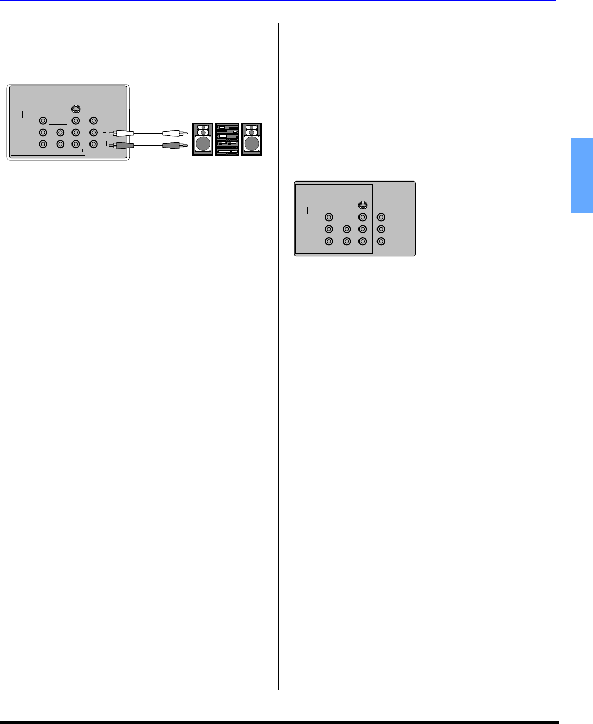
Amplifier Connection (TO AUDIO AMP)
Connect to an external audio amplifier input for listening to
a stereo system.
Note:TO AUDIO AMP terminals cannot be connected directly
to external speakers.
Note:Rear A/V jacks diagram may vary, depending on model.
Please refer to the FEATURE CHART on page 3 for your
model’s capabilities.
Audio Adjustments
• Select TV SPEAKERS ON from AUDIO menu.
• Set amplifier volume to minimum.
• Adjust television volume to desired level.
• Adjust amplifier volume to match the television.
• Select SPEAKERS OFF & VARIABLE AUDIO OUT from
AUDIO menu.
• Volume, mute, bass, treble and balance are now
controlled through the television.
Note:Select SPEAKERS OFF & FIXED AUDIO OUT to control
audio functions through the external amplifier.
Program Out Connection (PROG OUT)
(models CT-32SC14, CT-32SL14 and CT-36SL14 only.)
To use the television audio and video with optional equipment.
Connect the PROG OUT and TO AUDIO AMP connections on the
back of the television.
Notes:
• When a component input video signal is connected to
VIDEO 1(Y, P
B
, P
R
) terminals, and the TV main picture is
Component, the Program output video will be luminance
signal (no color).
• When S-VIDEO input signal is used for TV main picture,
the Program output video signal will be luminance signal
(no color).
Note:Rear A/V jacks diagram may vary, depending on model.
Please refer to the FEATURE CHART on page 3 for your
model’s capabilities.
Procedure
• Connect optional equipment to PROG OUT and TO
AUDIO AMP R/L.
• PROG OUT terminal display is the same as on-screen
display.
• See optional equipment manual for further instructions
for recording and monitoring.
TERMINALS ON BACK OF TV
VIDEO / Y
P
B
P
R
COMPONENT
VIDEO INPUT
INPUT 1 INPUT 2
S-VIDEO
PROG
OUT
VIDEO
TO AUDIO AMP
L
R
AUDIO
L
L
R
R
External Amplifier
CABLES NOT SUPPLIED
CABLES NOT SUPPLIED
TERMINALS ON BACK OF TV
VIDEO / Y
P
B
P
R
COMPONENT
VIDEO INPUT
INPUT 1 INPUT 2
S-VIDEO
PROG
OUT
VIDEO
TO AUDIO AMP
L
R


