19
8/27/08
RTR0542 and RTR0550 Rotary Tillers 311-464M
Land Pride
Section 4: Maintenance and Lubrication
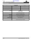
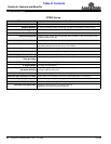
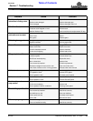
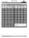
Table of Contents
Section 4: Maintenance and Lubrication
Maintenance
!
CAUTION
For safety reasons, each maintenance operation must be
performed with the tractor’s PTO disengaged, the Tiller
lowered completely to the ground or on safely supported
blocking, tractor engine shut off and ignition key removed.
Proper servicing and adjustment is the key to the long life
of any implement. With careful and systematic
inspection, you can avoid costly maintenance, time and
repair.
After using your tiller for several hours, check all bolts to
be sure they are tight.
Replace any worn, damaged or illegible safety labels by
obtaining new labels form your Land Pride Dealer.
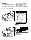
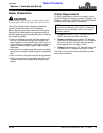
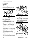
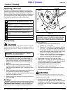
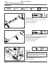
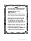
TIne Replacement
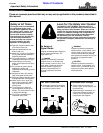
Figure 4-1
Tine Replacement
Refer to Figure 4-1:
!
WARNING
Worn tines may be very sharp!
7. Remove two 1/2”-20 x 1 1/4” GR5 hex head cap
screws (#1), hex nuts (#2) and lockwashers (#3).
Remove tine (#4).
8. Attach each new tine to the flange making certain it is
mounted so that the cutting edge crosses over the
flange and leads in rotation as shown in Figure 4-1.
9. Replace cap screws and fasteners (#1, #2 & #3).
Tighten nuts to proper torque. See The Torque
Values Chart in the “Appendix” section on page 26.
23779
IMPORTANT: Replace tines with genuine Land Pride
tines only.
When ordering replacement tines, be sure to order
both right and left hand tines. Always install tines with
cutting edge facing direction of rotor shaft rotation.
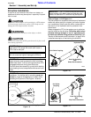
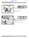
Driveline Protection
!
CAUTION
Engage parking brake, disengage PTO, shut off tractor, and
remove key before making any of the following adjustments.
Tiller drive components are protected from shock loads
by either a two plate friction clutch or a shear bolt. Avoid
shear bolt failure by engaging the PTO slowly at low
engine rpm. See your Land Pride Dealer when replacing
shear bolts. Torque shear bolt nuts to 8 ft. lbs.
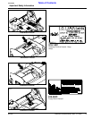
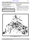
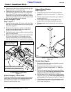
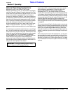
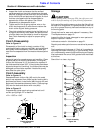
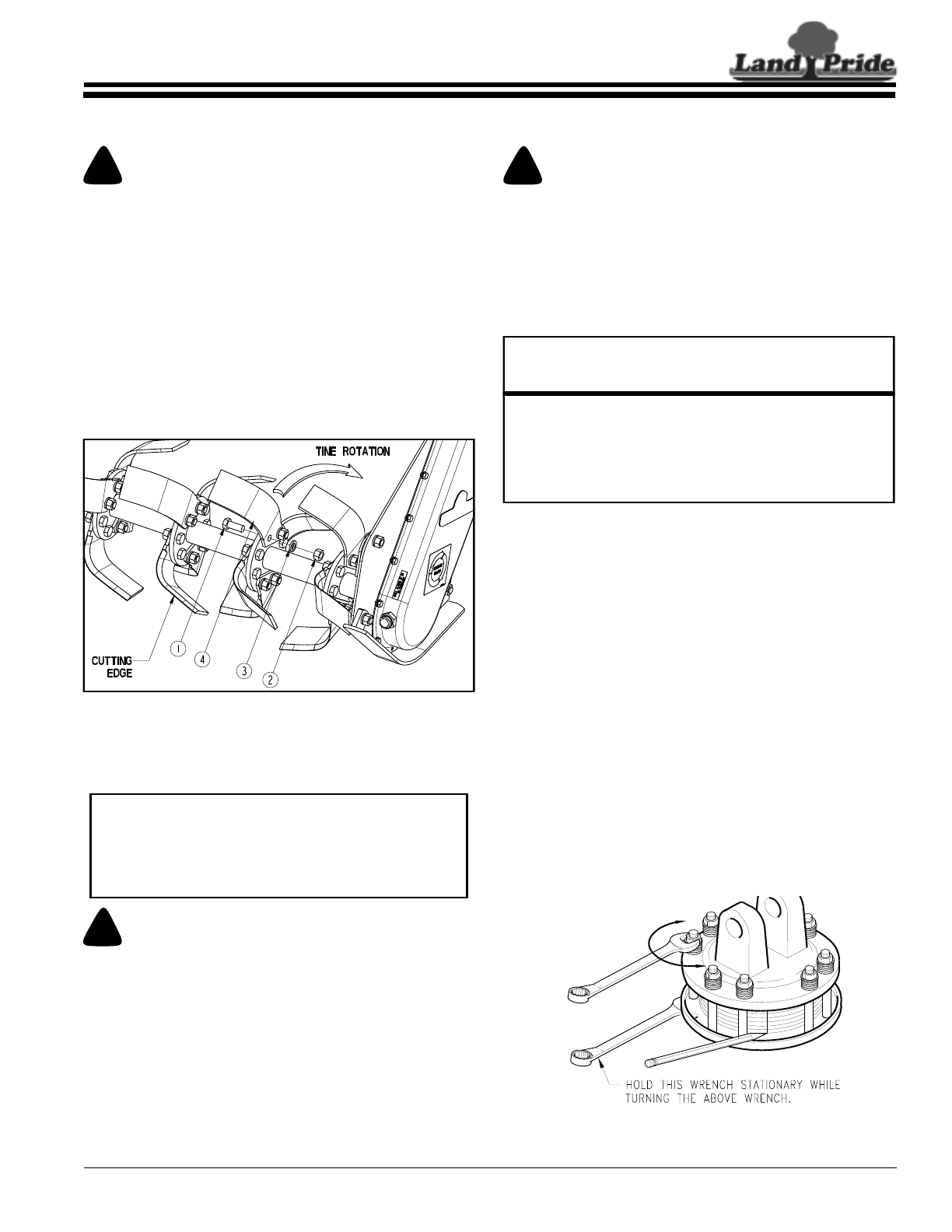
Clutch Run-In
Friction clutches should be “run-in” prior to initial
operation and after long periods of inactivity. To prevent
driveline and gearbox damage, repeat “Run-In”
instructions at the beginning of each season and when
moisture and/or condensation seizes the inner friction
plates.
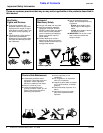
Refer to Figure 4-2 on page 19
1. Using a pencil or other marker scribe a line across the
exposed edges of the clutch plates and friction disks.
2. Carefully loosen each of the 8 spring retainer nuts by
exactly 2 revolutions. It will be necessary to hold the
hex end of the retainer bolt in order to count the exact
number of revolutions.
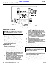
3. Start the tractor and engage the driveline drive for
2-3 seconds to permit slippage of the clutch
surfaces. Disengage the driveline, then re-engage a
second time for 2-3 seconds. Disengage driveline,
shut off tractor and remove key. Wait for all
components to stop before dismounting from tractor.
Clutch Run-In
Figure 4-2
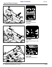
Shear Bolt and Lock Nut Part Numbers
Part No. Part Description
RTR05
165.000.509 BOLT & NUT M6X40 CL 8.8
(Torque nut to 8 ft. lbs.)
Note: If M6 bolt shears excessively, a 1/4”-20 GR5 bolt & nut
may be used. A 1/4” -20 GR8 bolt is not recommended as it may
cause damage to profiles, tiller frame and/or components.
1369