TK-7150
44
CN201
CN202
VR700
VR1
L201
1
2
L205
L206
CV
L207
L208
L209
L210
1
2
TC501
TX
TC502
RX
CV
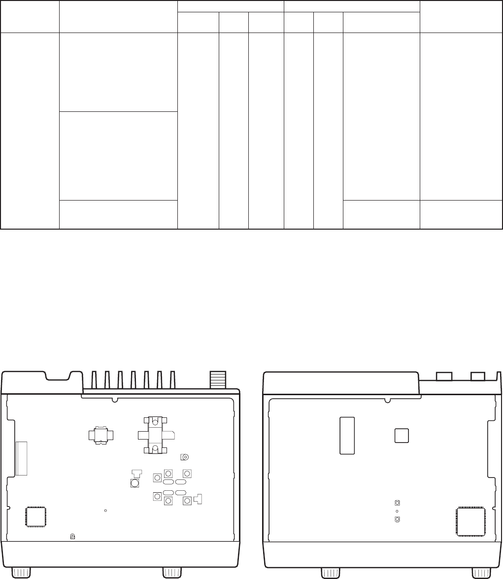
7. Adjustment Points
7-1. Component Side View 7-2. Foil Side View
VR1 : TX high power (High)
VR700 : MIC seisitivity
TC501 : PLL lock voltage (TX)
TC502 : PLL lock voltage (RX)
L201 : AF coil adjustment
L205,207,209 : MCF (Wide)
L206,208,210 : MCF (Narrow)
Item Condition
Measurement Adjustment
Specifications/
Remarks
Test-
equipment
Unit Terminal PartsUnit Method
ADJUSTMENT
21. Squelch 1) CH-SIG : 1-1 SSG Rear ANT Front
Selector
Adjust to point of Set the value to 255.
open Select Sql_O_ _ _ _✽✽✽ panel panel knob opening squelch Adjust the SSG out-
• Wide in tuning mode put to “Condition”.
SSG output : Value when 3dB AF VTVM EXT.SP Then, decrease the
is subtracted from the Distortion value to the point of
sensitivity value of 12dB meter opening the squelch.
SINAD.
Oscilloscope
4Ω dummy
• Narrow 2) [PF5] key : Set the narrow load
n_ _
Sql_O_ _ _ _✽✽✽
in tuning mode
SSG output : Value when 4dB
is subtracted from the
sensitivity value of 12dB
SINAD.
•
Wide/Narrow
3) SSG output : OFF Check Squelch must be
closed.
Note : When you change the Squelch adjustment value, connect all necessary measuring equipment (as stated in the adjustment procedure), then
adjust it to the SSG output value.


