10
30 kW Generator
Read this operator’s manual and Important Safety Instructions before operating your generator.
Compare the illustrations of this model with your generator to familiarize yourself with the locations of various controls
and adjustments. Save this manual for future reference.
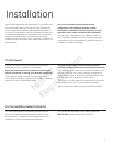
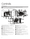
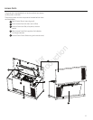
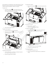
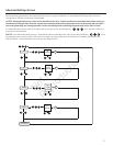
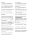
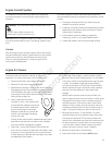
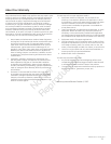
Controls
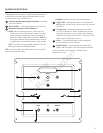
Generator is pictured with access doors removed for clarity
and screen guard open for clarity.
A
Exhaust Port — High-performance muffler lowers engine
noise to comply with most codes.
B
Engine Label — Identifies engine model and type.
C
Oil Dip Stick — Used to check the engine oil level.
D
Roof Access Opening — Provides access to control panel,
oil filter, etc.
E
Circuit Breaker Enclosure — Equipped with removable top
to assist with conduit connection.
F
Control Panel — Used for various test, operation and
maintenance functions. See System Control Panel.
G
Air Cleaner — Protects engine by filtering dust and debris
out of intake air.
H
Fuel Selection Switch — Select natural gas or liquid
propane (LP vapor) supply.
J
Oil Fill Cap — Remove to service the engine with
recommended oil.
K
Coolant Fill — Provides access for filling engine coolant.
L
Coolant Recovery Bottle — Provides visual indicator of
engine coolant level.
M
Fuel Inlet — Fuel supply is connected here.
N
ID Label — Identifies unit by serial number.
P
Rear Access Panel Opening — Provides access to various
components of generator.
R
Oil Filter — Filters engine oil to prolong system life.
S
Front Access Panel Opening — Provides access to various
components of generator.
T
Battery Location — Battery located for convenient access.
U
Fuel Type Selector — Position selector for Natural Gas (NG)
or Liquid Propane (LP vapor) supply.
B C D
E
F
G
T
S
R
L
K
J
P
N
M
H
A
Back Top
Front
U