GB-8
SRTZ2601F
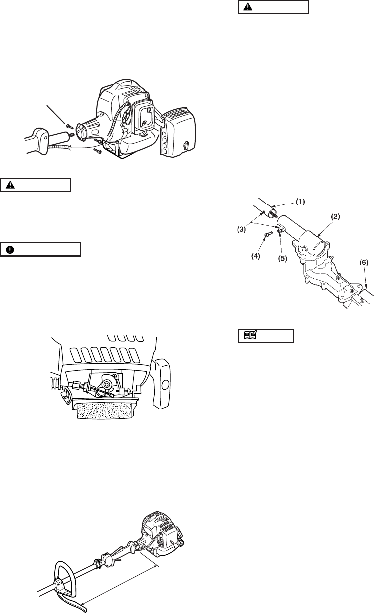
ATTACHING THE TRIMMING MECHANISM
WARNING
The blade has very sharp edges. Be sure to use pro-
tective gloves and protective cover whenever han-
dling it.
1. Remove the cap on the end of the main pipe.
2. Remove the screw and the fastening bolt screwed
into the end of the trimming mechanism.
3. Insert the end of the trimming mechanism into the main
pipe.
4. Align the locking holes and screw in the lock screw to
the bottom by hand, then secure it with the wrench
provided. Do not tighten up the lock screw with the
holes out of alignment, or the trimming mechanism
can be damaged.
NOTE
If the locking screw is tightened up with the holes out of
alignment, the cuttercase may be damaged.
5. Fasten the cuttercase fastening screw.
BALANCE UNIT
1. Put on strap and attach unit to strap.
2. Depending on the working posture, slide clamp up or
down until unit balances and the strap fits your body.
MOUNTING ENGINE
1. Push the drive shaft housing toward the clutch hous-
ing and move it by hand to check that the drive shaft
is engaged with the gears.
2. Insert the drive shaft housing into the clutch housing
until it bottoms, and align the positioning holes on the
clutch housing and the shaft tube and install the screw.
When difficult to engage, twist the engine slightly.
3. Fasten the clamp securely with two screws.
WARNING
Never use any screws other than those specified by
the manufacturer, or the engine can get loose, result-
ing in a hazardous event.
IMPORTANT
Tighten the screws gradually by turns.
CONNECTING THROTTLE WIRE
1. Remove the air cleaner cover.
2. Connect the end of the throttle wire to the joint on the
top of the carburetor.
CONNECTING SWITCH WIRES
•Connect the switch wires between the engine and the
main unit.
INSTALLING HANDLE
• Mount the handle to the shaft tube and clamp it at a
location that is comfortable to you.
6. Set up
Bolt
About 48cm
(1) Main pipe
(2) Trimming
mechanism
(3) Locking hole
(4) Lock screw
(5) Fastening screw
(6) Protective cover


