4
English Español
3. Setup 3. Montaje
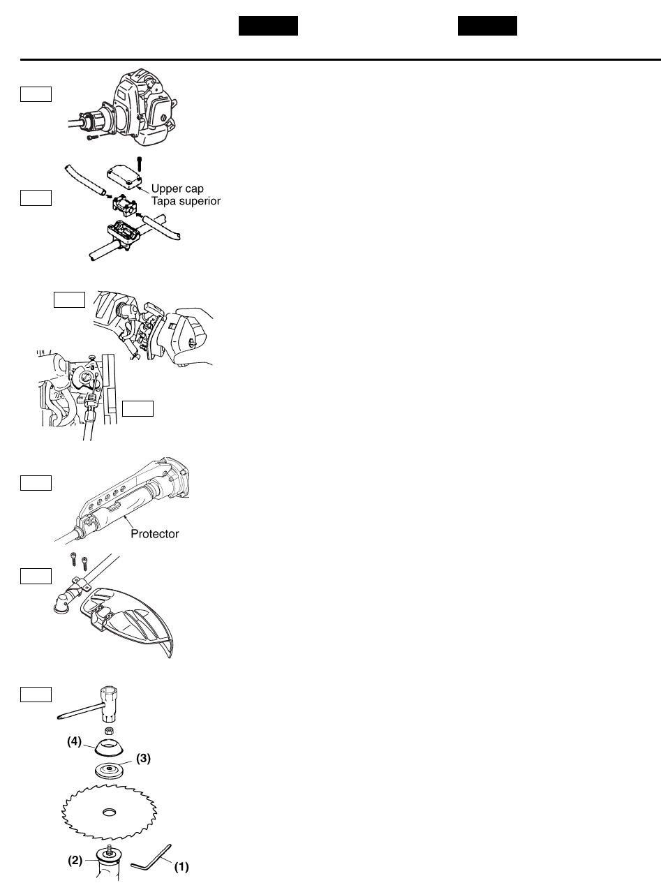
■ ENGINE
Using attached 4 socket screws, secure
the connection firmly with equal force.
■ HANDLE
1. Remove the upper cap from the
bracket.
2. Loosen the 4 bolts on the clamp and
insert the handles equally. Retighten
the bolts.
3. Put the handle assembly into the
bracket and put the upper cap over
it. Tighten the cap securely.
■ CONNECTING THROTTLE WIRE
1. Remove the air cleaner cover.
2. Connect the end of the throttle wire
to the joint on the top of the
carburetor.
■ PROTECTOR
Wrap the protector around the outer
pipe as shown in the figure, and fasten
the magic fastener.
■ BLADE GUARD
Attach the guard on the outer pipe. Fix it
with 2 bolts.
■ BLADE
1. Put the angled bar(1) into the side
holes of the inner holder and the
gearcase.
2. Remove the nut (Lefthanded) and
the outer holder(3) from the
gearshaft.
3. Put the blade onto the inner
holder(2). Make the marked side face
the holder.
4. Put the outer holder(3) onto the
gearshaft making the recessed side
face the blade.
5. Fasten the blade by the nut and the
cover(4).
[Tightening torque]
14.7 to 19.6 N·m (150 to 200 kg·cm)
■ MOTOR
Utilizando los 4 tornillos insertados,
asegure la conexión firmemente con la
misma fuerza.
■ MANGO
1. Retire la tapa superior del soporte.
2. Afloje los 4 tornillos de la abrazadera
e inserte los mangos
uniformemente. Apriete los tornillos.
3. Coloque el ensamble del mango en el
soporte y coloque la tapa superior
sobre éste. Apriete la tapa
firmemente.
■ CONEXIÓN DEL ALAMBRE DEL
ACELERADOR
1. Retire la cubierta del filtro de aire.
2. Conecte el extremo del alambre del
acelerador a la junta situada en la
parte superior del carburador.
■ PROTECTOR
Envuelva el protector alrededor del tubo
como se muestra en la figura y apriete
el sujetador.
■ PROTECTOR DEL UTENCILIO DE
CORTE
Coloque el protector en el tubo externo.
Fíjelo con 2 tornillos.
■ CUCHILLA
1. Coloque la barra angulada (1) en los
orificios laterales del soporte interior
y la caja de engranajes.
2. Retire la tuerca (a mano izquierda) y
el soporte exterior (3) del eje.
3. Coloque la cuchilla en el soporte
interior (2). Haga que la cara lateral
marcada se encuentre de frente con
el soporte.
4. Coloque el soporte exterior (3) en el
eje de engranajes haciendo que la
cara lateral cóncava se encuentre de
frente a la cuchilla.
5. Apriete la cuchilla con la tuerca y la
tapa (4).
[Par de torsión]
14.7 to 19.6 N·m (150 to 200 kg·cm)
F3-1
F3-2
F3-3
F3-4
F3-5
F3-6
F3-7


