


18
Run engine full throttle to make sure wheels do
not rotate. Readjust if any rotation occurs.
Repeat the whole process for the opposite side
and tighten the nuts against the ball joints.
Turn machine off.
Reinstall the seat rod and check the wiring har-
ness to the seat safety switch for a good connec-
tion and return the seat to the normal position.
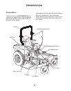
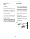
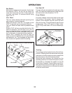
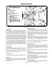
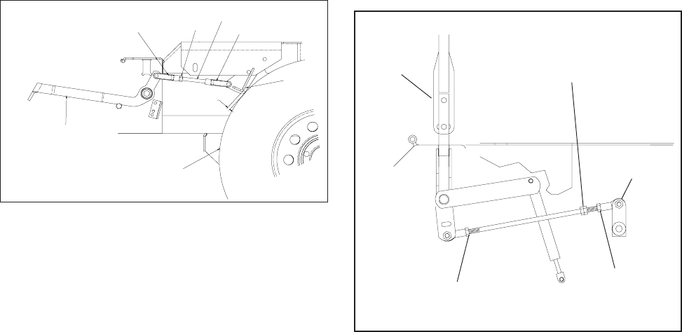
FIG - 6
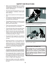
Begin with either side and put the motion control
lever into the neutral position. Adjust the motion
control linkage by rotating the double nuts in the
proper direction until the wheel stops rotating. FIG
- 6 Move the motion control lever forward then
into the neutral position and place it into the neu-
tral slot. The wheel must be stopped completely
at this point. Now do the same in reverse and re-
lease the lever. The lever should return to neutral
on its own.
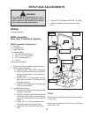
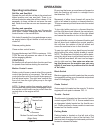
SETUP AND ADJUSTMENTS
Motion Control Linkage Adjustment
This adjustment must be made with the rear
wheels rotating. Raise the rear of the machine
and block it up so the wheels are free to rotate.
CAUTION: Keep hands, feet and clothing away
from rotating tires.
Start the engine. The park brake must be engaged
and the motion control levers in the neutral slots
to start the engine. Run the engine approximately
half throttle
Release park brake to allow the wheels to rotate.
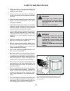
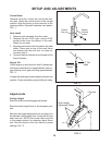
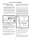
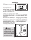
Park Brake Adjustment
For Models: ZMKW48191, ZMKW52231,
ZMKH52231, ZMKW61231
1. Stop engine and remove key, release park brake
and check the gap between the rear tire and the
brake arm. The gap should be 1/8” to 1/4”.
3. Make sure the brake arm on both sides does
not touch the tire when the brake is in the off
position. FIG - 5
2. If adjustment is needed, loosen the lock nut
next to the yoke. Remove the pin from the front
yoke so you can rotate the yoke on the adjust-
ment link until the proper gap is achieved.
Park Brake Lever
(in the off position)
Front Yoke
Lock Nut
Rear Tire
Adjustment Link
Yoke
Brake
Arm
1/8”-1/4”
Gap
FIG - 5
Turn Here
To Adjust
Loosen Here
Loosen Here
(Lt. Hand Thds.)
Motion
Control
Lever
Pump
Arm
Tilt seat forward and remove the seat rod so the
seat may rotate forward onto the frame.
Place a 2x4 board between the foot plate and the
center of the seat to engage the seat safety switch.
Loosen the nuts directly behind each ball joint on
both rods that connect the pump arm to the mo-
tion control assemblies. FIG - 6