


6
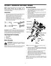
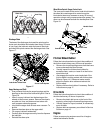
Attaching the Chute Assembly
NOTE: Your chute assembly may or may not be
assembled. If it requires assembly use the following
instructions.
Figure 3
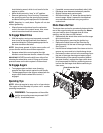
• Place chute assembly over chute opening, with the
opening in the chute assembly facing the front of
the unit. Place chute flange keepers beneath lip of
chute assembly, with the flat side of chute flange
keeper facing downward.
• Insert hex cap screws up through chute flange
keeper and chute assembly as shown in Figure 3.
Secure with hex flange locknuts. Tighten with two
7/16” wrenches. Do not over tighten.
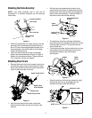
Attaching Chute Crank
• Remove the hairpin clip from the upper chute crank
and slide the upper chute crank through the upper
chute crank bracket and into the lower chute crank.
A pair of pliers may help in this job.
Figure 4
• Align the two holes on both chute cranks and
secure with the hairpin clip removed earlier. See
Figure 4.
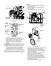
• With the hex nuts loosened on the lower chute
crank bracket (see Figure 5) adjust the bracket so
that the spiral on the chute crank fully engages the
teeth on the chute assembly. Tighten the nuts on
the lower chute crank bracket securely.
Figure 5
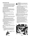
• The cable ties normally are loosely installed on
each side of the lower handle at the factory. Pull the
cable ties tight to secure. Trim excess from the
ends of cable ties.
• If not already attached, slip the cables that run from
the handle panel to the discharge chute into the
cable guide located on top of the engine.
See Figure 6.
Figure 6
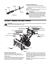
• Wrap the wire from the head lamp down the right
handle until the wire can be plugged into the
alternator lead wire under the fuel tank.
Figure 7
Chute Assembly
Hex Screw
Hex Lock Nut
Chute Flange
Keeper
Upper Chute Crank
Lower Chute Crank
Hairpin Clip
Upper Chute
Crank Bracket
Chute Directional
Control
Lower Chute
Bracklet
Chute
Assembly
Lock Nuts
Cable
Discharge
Chute
Guide
Cables
Alternator Lead
Lamp Wire
Alternator
Lead
NOTE:
Wheels are omitted from illustration for clarity.