


11
Sharpening Or Replacing Chipper Blades
NOTE: When tipping the unit, empty the fuel tank and
keep spark plug side up.
• Disconnect the spark plug wire and ground it
against the engine.
• Remove the flail screen as instructed in the
previous section.
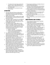
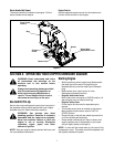
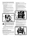
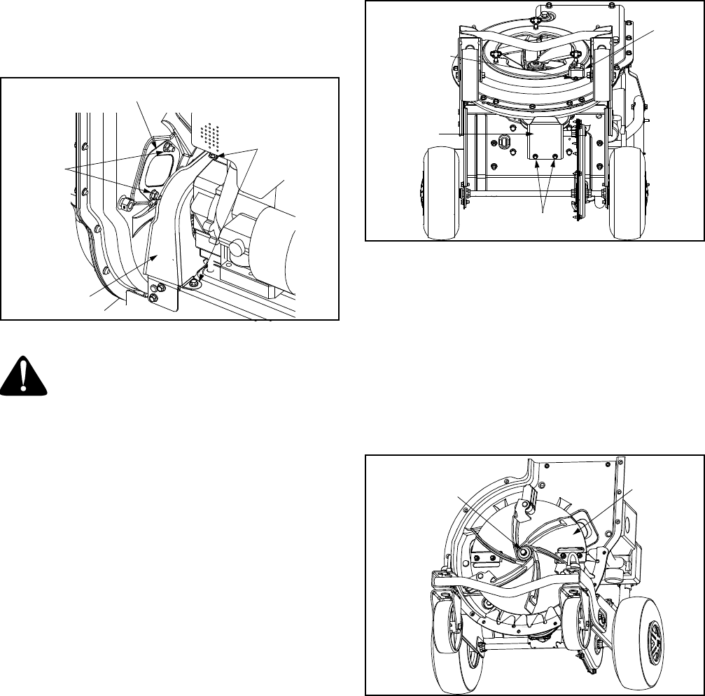
• Remove the plastic belt cover on the front of the
engine by removing the two self-tapping screws.
See Figure 11.
• Remove the access plate by removing two hex lock
nuts. See Figure 11.
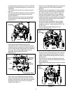
• Locate one of the chipper blades in the access
opening by rotating the impeller assembly by hand.
Remove the chipper blade using a 3/16” allen
wrench and a 1/2” wrench.
• Remove other blade in the same manner to replace
or sharpen.
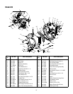
Figure 11
WARNING: Use caution when replacing
the blades, wear heavy gloves to avoid a
contact injury with the weld bolts or the
housing while loosening or tightening the
blades.
• When sharpening blades, follow the original angle
of grind. Also, make sure to remove an equal
amount from each blade and torque hardware 250 -
300 in. lbs.
NOTE: Make certain blades are reassembled with the
sharp edge facing upward.
Belt Removal And Replacement
NOTE: Because the engine on this has a tapered
crankshaft, a special impeller removal tool (part number
753-0638) is required to remove impeller assembly.
Contact your local service dealer.
• Disconnect the spark plug wire and ground it away
from the spark plug.
• Drain the gasoline and oil from the chipper
shredder vacuum.
• Remove the three wing nuts that secure the nozzle
to the outer housing and remove the nozzle. Refer
to Figure 2.
• Remove the vacuum bag from the unit.
• Remove the discharge chute as instructed in the
previous section Removing The Flail Screen.
• Remove the plastic belt cover on the front of the
engine by removing two self-tapping screws. Refer
to Figure 11.
• Tip the unit backward so that it rests on the
handles.
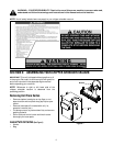
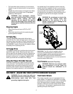
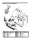
• Remove the lower belt guard by removing the two
self-tapping screws. See Figure 12.
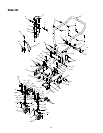
Figure 12
• Remove the safety switch from the front of the outer
housing by removing the two self-tapping screws.
See Figure 12.
• Remove the two hex bolts and hex lock nuts which
extend through the housing. Lift the flail screen out
of the housing. Refer to Figure 10.
• Remove the outer housing and housing blades by
removing the fourteen self-tapping screws.
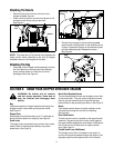
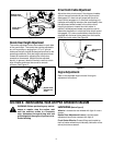
• Remove the hex bolt, lock washer, and flat washer
that secures the impeller assembly to the
crankshaft. See Figure 13.
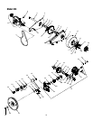
Figure 13
Belt
Cover
Self-Tapping
Screws
Access Plate
Hex
Lock Nuts
Safety
Switch
Self-Tapping
Screw
Lower
Belt Guard
Self-Tapping
Screws
Impeller
Assembly
Hex Bolt
Lock Washer
Flat Washer