


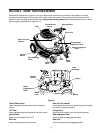
8
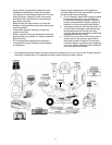
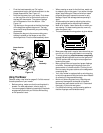
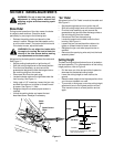
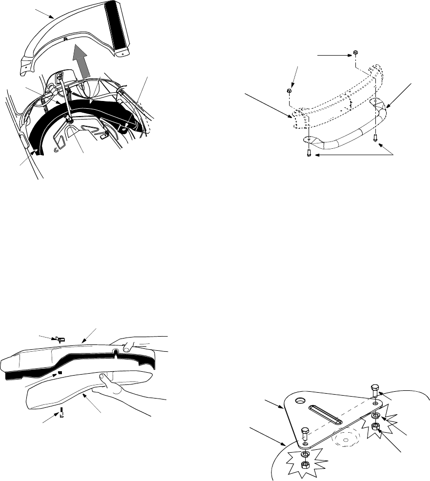
• Pivot the hood assembly up and lower the cutting
height adjustment lever to the lowest position.
• Remove the two wing nuts (A and B in Figure 4 )
from two ends of the grasscatcher chute.
• Loosen the two wing nuts (C and D in Figure 4 ) in
the middle of the chute. Do not remove. All four
wing nuts hold the chute to the deck frame.
• Slide the grasscatcher chute to the right and out of
the deck frame. Slide the side-discharge chute in
and place it on the deck so that the four wing nut
positions align with those on the deck.
• Reinsert wing nuts A and B. Tighten to secure.
Tighten the two wing nuts C and D.
Figure 4
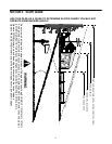
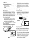
Attaching Mulch Plug
While operating your rider mower, you have three
options: (i) to collect grass clippings in the grass
catcher, (ii) to discharge grass clippings on the side, or
(iii) to mulch grass and recirculate clippings back to the
lawn. For the third option, attach the mulching plug to
the side-discharge chute and then to the deck.
• Put two hex bolts through the mulching plug at the
respective openings. See Figure 5 .
Figure 5
• Place speed nuts over the hex bolts.
• Insert the plug into the side-discharge chute
aligning the two slots on two sides of the side-
discharge chute with those on the mulching plug.
• To attach the mulching plug now to the unit, follow
instructions on previous page to attach side-
discharge chute to the deck.
• Place wing nut on each of the hex bolts and thread
a few turns. See Figure 5 . Check that the mulch
plug is aligned correctly within the discharge chute.
• Tighten both wing nuts
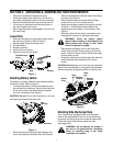
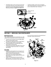
Attaching Bumper (Optional)
• Remove bumper from the grass catcher.
• Loosen and remove the two hex bolts and lock nuts
from the front rail on the rider mower. See Figure 6 .
• Align the two holes on the bumper tube with the
corresponding holes on the rider frame (from where
you removed the hardware). See Figure 6.
• Re-insert the two hex bolts through the bumper and
the rider frame and secure with the two lock nuts.
See Figure 6 .
Figure 6
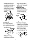
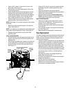
Attaching Hitch Plate (Optional)
The hitch plate, if equipped, was loosely attached to the
rear frame of the rider for shipping purposes.
• Loosen the nut attaching the hitch plate to the
frame and swing the plate outward. Make sure that
the wider side of the hitch plate aligns with the rear
frame as shown in Figure 7 .
• Remove the hex bolt, lock washer and hex nut from
the other end of the rear frame. Save the hardware.
• Align the hole on the hitch plate with the
corresponding hole on the rear frame assembly
(from where you removed the hardware).
• Re-insert the hex bolt through the hitch plate and
the rear frame. Secure with the lock washer and
hex nut removed earlier. See Figure 7 . Tighten
both sets of hardware.
Figure 7
Grass Catcher
Chute
Side-
Discharge
Chute
Wing
Nut A
Wing
Nut D
Wing
Nut B
Wing
Nut C
Side Discharge Chute
Mulching
A
B
Wing Nut
Speed
Nut
Plug
Hex Bolt
Lock
Nut
Bumper
Hex Bolt
Rider Frame
Rail
Rear
Hitch Plate
Hex Bolt
Lock
Washer
Hex
Frame
Nut