


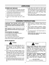

CONTROLS
IGNITION SWITCH
The ignition switch is located on the dashlo3ard. The
engine is started by turning the key to the ST _,RTposi-
tion. When the engine is running, leave the {ey in the
ON position. To stop the engine, turn the _ey to the
OFF position. See figure 7.
_b WARNING: Remove the key from the trac-
tor when the tractor is not in u.,e to pre-
vent accidental starting.
THROTTLE CONTROL
The throttle control is located on the dashbo=Lrd and is
used to regulate the engine speed. To get -naximum
efficiency from cutting, the throttle should )e in the
FAST position when operating the mower. Se_ figure 7.
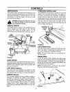
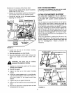
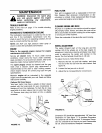
Light
Ignitior
Choke, "__ Lift
Throttle _ Lever
Ammeter
[Optional)
Clut "h-Brake
Pedal
FIGURE 7.
CHOKECONTROL
The choke control is located on the dashboard and is
operated manually. Details for the choke openation are
covered in the separate engine manual packed with
your unit. See figure 7.
LIGHT SWITCH (Optional)
The head lamps are operated by pushing
switch located on the dashboard. The head I_
only operate when the engine is running. See
AMMETER (Optional)
The ammeter registers the rate of battery ¢
discharge. The ammeter will register on the q
ing side with starting the engine. It should re
the opposite side (charging) when the engin
ning in the fast position until the battery is c(
charged. With a fully charged battery or
engine idling, the ammeter will not show a ch_
figure 7.
the light
imps will
figure 7.
harge or
fischarg-
;lister on
is run-
mpletely
with the
rge. See
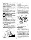
HYDROSTATICCONTROL LEVER
The hydrostatic control lever is located on top of the
fender on the right side of the tractor. This single con-
trol lever, connected to the hydrostatic transmission,
controls both the speed and direction of the tractor.
Infinite speed control is achieved by moving the control
lever forward or backward. The farther forward or back-
ward you move the control lever, the faster you will
travel. Pulling the control lever into neutral (N) area will
stop the tractor. See figure 8.
Hydrostatic /
Control _-_
Lever
FIGURE 8.
CLUTCH-BRAKEPEDAL
The clutch-brake pedal is located on the left side of the
tractor. See figure 7. Depressing the pedal returns the
drive unit to neutral (N) and applies the brake.
NOTE: The clutch-brake pedal must be depressed to
start the engine.
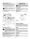
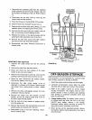
PARKING BRAKE
To set the parking brake, depress the clutch-brake
pedal, pull up the parking brake knob and release the
clutch-brake pedal. Itwill stay in the raised position. To
release the parking brake, depress and release the
clutch-brake pedal. See figure 9.
NOTE: The parking brake must be set if the operator
leaves the seat with the engine running.
FIGURE 9.