


7
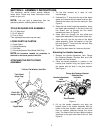
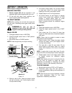
1. Remove the T-handle, nut, hairpin clip, and
rubber washer from the ends of the handle
adjustment rod. Slide the rod up through the left
side of the bracket on the front of the handle
assembly. Refer to Figure 7.
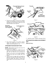
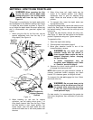
2. Slide the rubber washer on the unthreaded end
of the handle adjustment rod. Insert the end of
the handle adjustment rod into the positioner
bracket beneath the handle, on top of the tine
shield. See Figure 9. Secure with hairpin clip.
3. Reinstall the nut and T-handle.
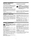
ATTACHING THE CLUTCH CABLE
Figure 10
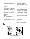
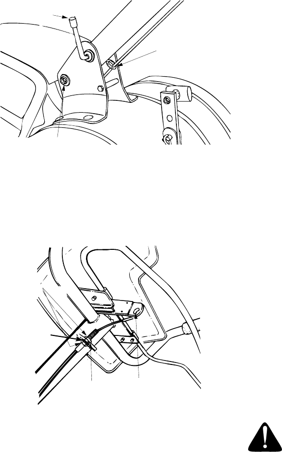
1. Route the clutch cable underneath the handle
and through the cable clip. Be careful not to
bend or kink the cable. Refer to Figure 10.
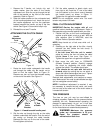
Remove one hex nut from the threaded casing
on the end of the cable. See Figure 11.
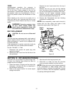
Figure 11 Viewed beneath handle panel.
2. Slip the wire up through the slot on the cable
bracket underneath the handle. Push the end of
the casing up through the cable bracket.
Rethread the hex nut on the end of the cable.
Do not tighten at this time.
3. Pull the cable upwards to obtain slack, and,
from right to left, hook the “Z” end of the cable
into the bracket on the clutch control (beneath
the handle panel) as shown in Figure 11.
Tighten the nut against the cable bracket.
NOTE:
Do not overtighten control wire. Too much
tension may cause it to break.
FINAL CLUTCH ADJUSTMENT
IMPORTANT: Service the engine with oil
and
gasoline before checking this adjustment. Refer to
the separate engine manual packed with your tiller.
1. Position the tiller so the front counterweight is
against a solid object, such as a wall. With the
gear selection lever in NEUTRAL, start the
engine. Refer to Operation section.
NOTE:
Keep hands out of belt area while unit is
operating.
2. Standing on the right side of the tiller, visually
examine the belt (inside the belt cover). It
should not be turning.
If the belt turns with the unit in neutral,
adjust by moving the hex nut below the cable
bracket
down
a few turns. See Figure 11.
Tighten the upper hex nut against the bracket.
3. Now move the shift lever to FORWARD
(Wheels Forward) position. Carefully engage
the clutch by squeezing the clutch handle
against the handle. The wheels should spin.
4.
If the wheels do not spin with the unit in
forward,
adjust by moving the hex nut which is
above the cable bracket
up
a few turns. Tighten
the bottom hex nut against the bracket.
Recheck both adjustments, and readjust as neces-
sary. Make certain hex nuts at cable bracket are tight
(do not overtighten control cable).
NOTE:
If additional adjustment is required, it may
be necessary to remove the belt cover, and move
the hex nuts at the other end of the clutch cable to
increase belt tension.
TIRE PRESSURE
The tires on your unit may be over-inflated for
shipping purposes. Reduce the tire pressure before
operating the unit. Recommended operating tire
pressure is approximately 14 p.s.i. on 14 inch tires
and 20 p.s.i. on 16 inch tires. (Check sidewall of tire
for tire manufacturer’s recommended pressure).
WARNING:
Maximum tire pressure
under any circumstances is 30 p.s.i.
Equal tire pressure should be
maintained on both tires.
Handle
Adjustment
Lock
Cable
Clip
Flange Lock Nut
Washer
Hex
Nuts
Slot in
Cable
Bracket
“Z” End
of Cable
Lock