OPTIONAL PARTS
-
38
-
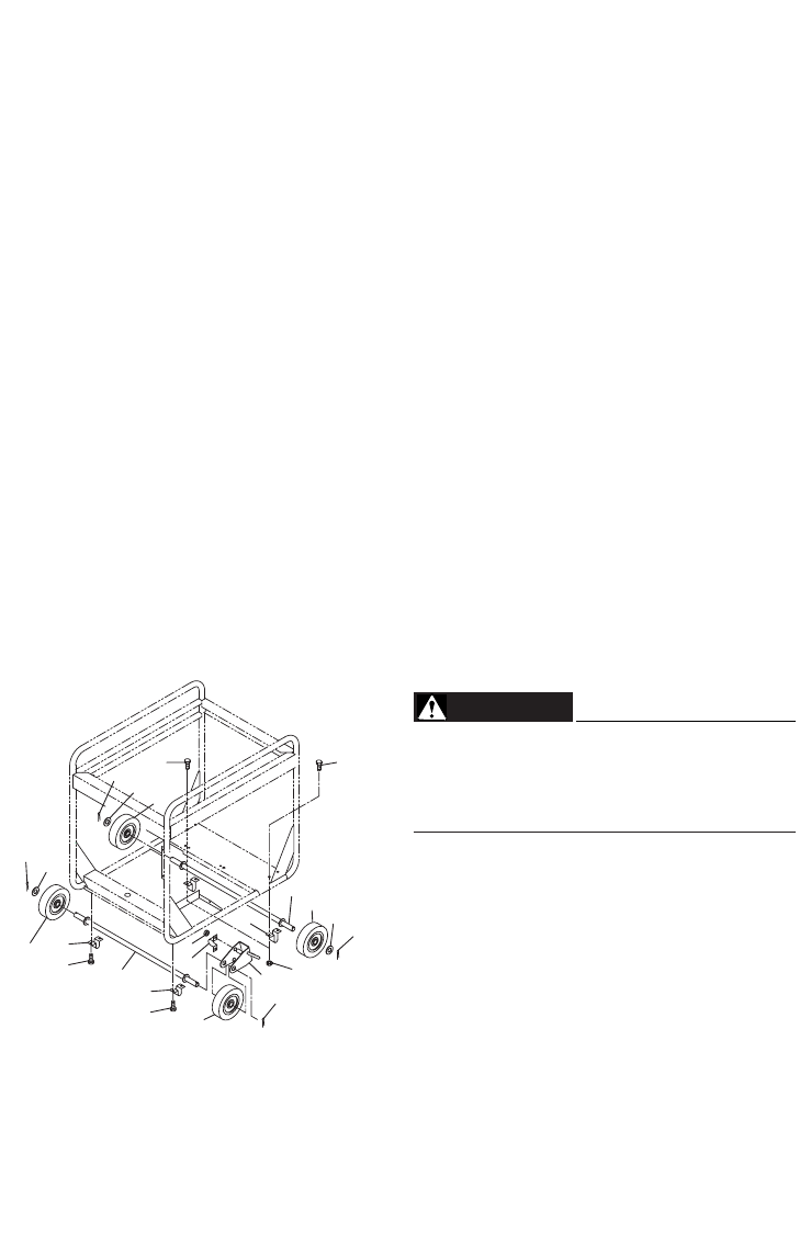
"HOW-TO" INSTALL THE WHEEL
(1) Checking of supplied accessories
(2) Tool preparation
Hoist or square bar (100 mm (3.94 in) by 100 mm (3.94 in), length : 700 mm (27.56 in))
Plier
Spanner or socket wrench (12 mm (0.472 in)), 2 units
(3) Installation procedures
(a) Raise the generator by about 100 mm (3.94 in), with hoist or with square bar put under
the bottom panel.
(b) Attach wheel mounting parts
, ,stopper , using clamp and wheel , to
wheel shaft
.
Then check that wheel
is rotated smoothly. If moving turns out to be too compli-
cated, assemble them together using grease. (4 locations / 2 pieces)
(c) Bend the tip of
according to the shape of wheel shaft as possible.
(d) Attach the assembled shaft to the foundation plate of the engine, using
, , and .
(e) Attach the other shaft to the foundation plate of the generating unit, using
and .
(
is not used.)
The tightening torque of bolts should be
20 to 25 Nm (2.0 to 2.5 kg-m).
REMOTE CONTROL UNIT
When the remote control unit is connected, the engine will not start unless both starter
switch on the control panel and the engine switch on the remote control unit are switched
on.
If you provide the generator with wheels,
always be sure to place the generator on
a level surface, locking the wheel with
the stopper and /or chocking the wheels.
WARNING
EF12000DE排対_GU1763 03.2.4 1:54 PM ページ38


