


Xantrex RV Series Inverter/Charger Owner’s Manual
19
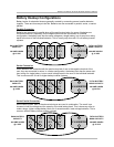
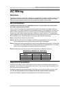
AC Wiring for Stacked Inverters
Due to the neutral ground switching design of the RV Series Inverter/charger, it is mandatory that
the AC input and AC output neutrals be isolated from one another. In a stacked pair configuration,
connect the two AC input neutrals together then the two AC output neutrals and then attach each
pair to isolated neutral locations.
Operation
The power switch of one unit turns both inverters on and off—this unit becomes the “master.” The
other unit is the “slave” and will follow the master throughout its modes of operation. Whichever
unit is turned on first becomes the master inverter.
For example, the inverters will both charge when AC line power is available to the master unit.
This will take place after the generator spin-up delay of 20 seconds (minimum) has passed and
the inverter has synchronized to the generator’s output. Accordingly, both units will transfer back
to inverter mode when the master unit senses a loss of AC input power.
The only situation in which the slave may shut down the master inverter is during fault conditions
such as high/low battery, over-current, or over-temperature conditions. Both inverters will auto
reset after a fault condition has been cleared. The exception is that an over-current condition will
generate a shutdown for both inverters that will require a manual restart of the system.
NOTE: The RV series inverters, unlike the “U series,” are series stacking, meaning the outputs
are connected in series providing 120/240 VAC output with twice the power at 240 VAC. The RV
inverters cannot be paralleled for twice the power at 120 VAC.
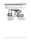
Theory of Operation
The inverter is designed to accept power input from single-phase, 3-wire 120/240 VAC system,
120 volts to each inverter. The HOT IN terminal of each inverter accepts one leg of 120 volts each
and the NEUTRAL IN terminals of both inverters are tied together and connected to the power
source neutral leg.
Any AC loads being powered while AC input is present to the inverters will be in addition to the
power being drawn for battery charging. Each unit of the pair can provide full pass-through current
of 50 amps for 120-volt systems.
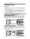
When AC input power is lost, the units switch from charger to inverter mode. Once this switch is
made 120 VAC is available from each individual inverter, or 240 VAC is available across the HOT
OUT terminals of the stacked pair.
Stacked inverters will typically support about twice the surge power of one stand-alone unit. For
example, an RV3012 stacked pair will surge about 9000 watts of incandescent lights at 240 VAC.
Keep in mind that typical incandescent light bulbs require about five times normal run current at
startup.