


1110
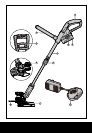
2-in-1 Cordless Grass Trimmer/Edger
EN
1110
ASSEMBLY INSTRUCTIONS
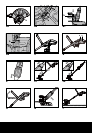
1. ASSEMBLY OF THE SAFETY GUARD
(See Fig. A1, A2)
Fix the safety guard to the trimmer head
making sure the sides are located into the
grooves on the trimmer head.
Secure the safety guard onto the trimmer
head with the screw provided (on the inside of
the guard).
2. ASSEMBLY OF THE EDGER WHEEL
(See Fig. B1, B2)
With the tool rightside up, slide the edger
wheel assembly onto the metal plate located
on the side of the trimmer head. Make sure
the groves of the edger wheel assembly locks
onto the metal plate, you will hear it click into
place.
To remove the wheel assembly, press the
release button (b) on the wheel and pull the
wheel assembly upward.
OPERATION INSTRUCTIONS
NOTE: Before using the tool, read the
instruction book carefully.
1. CHARGING YOUR BATTERY PACK
WARNING: The charger and battery
pack are specifically designed to work
together so do not attempt to use any other
devices. Never insert or allow metallic objects
into your charger or battery pack connections
because an electrical failure and hazard will
occur.
2. BEFORE USING YOUR CORDLESS
GRASS TRIMMER
When you charge the new battery or one
which has not been used for long periods of
time, it may not reach full charge until after
you have discharged it fully and recharged it
several times.
3. TO REMOVE OR INSTALL BATTERY
PACK (See Fig. C)
Locate latches on side of battery pack and
depress both sides to release battery pack
from your grass trimmer. Remove battery pack
from your grass trimmer. After recharge insert
the battery pack into grass trimmer’s battery
port. A simple push and slight pressure will be
sufficient.
4. SAFETY ON/OFF SWITCH (See Fig. D)
Your switch is locked off to prevent accidental
starting. Depress lock off button (b) then on/off
switch (a) and release lock off button (b). Your
switch is now on. To switch off just release the
on/off switch.
WARNING: The cutting head
continues to rotate after the
trimmer has been switched off, wait until
it has stopped then lay down the tool.
5. ADJUSTMENT OF THE TELESCOPIC
SHAFT (See Fig. E)
Unscrew the locking knob in the direction
indicated to unlock.
Adjust the length of the telescopic shaft to the
most comfortable length.
Tighten the lower locking knob.
6. MAIN HANDLE ROTATION
(See Fig. F1, F2)
While holding the trimmer head, pull upward
on the upper shaft and rotate it 90 degrees
clockwise then allow it to drop back into the
lower shaft coupling. When released back into
the lower shaft coupling, the upper shaft will
be locked into position automatically.
7. ADJUSTMENT OF AUXILIARY HANDLE
(See Fig. G)
Pull up the auxiliary handle locking lever .
Hold the locking lever and rotate the auxiliary
handle to the most comfortable and balanced
position
8. ADJUSTMENT OF THE TRIMMER
HEAD ANGLE TO THE SHAFT (See Fig. H)
Grip the trimmer head with one hand and
the shaft with the other. Change the angle by
applying adequate force. You will hear a heavy
click for each angle adjustment, which is part
of the ratchet mechanism. The clicking sound
is normal and is not a defect of the tool.