


4
VEHICLE PREPA R ATION
The 12 volt electric seeder can be mounted on most all
terrain vehicles.
The ATV must have a 12 volt electrical system or you
need to supply a separate 12 volt battery to power the
spreader fan motor.
Be sure tires and rims are in good condition. Inflate tires
to the proper recommended air pressure.
PACKING
Most ATV Broadcast Seeder-Spreaders are packaged
partially assembled in one carton consisting of: a basic
seeder unit, a scale plate with rod assembly, a mounting
frame and a mounting frame hardware kit.
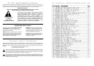
ASSEMBLY & MOUNTING
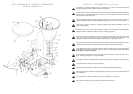
Lower Mounting Bracket – Turn to the drawing that
shows the mounting bracket and parts required for your
particular make and model vehicle.
Assemble the parts as shown in the drawing. We
suggest keeping all bolts loose until all bolts are in place
– then tighten all clamps and bolts securely.
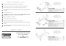
Seeder Mounting – Slide the seeder/spreader unit
down over the up-right on the lower mounting bracket
and line up holes. Insert the
1
/
4
” x 2” hex head bolt and
fasten the two together securely.
Bolt the scale plate and control rod assembly on the
front left hand corner of the main seeder frame. Two
round head
1
/
4
” – 20 x
1
/
2
bolts are provided in the
hardware package for this. Place the end of the control
rod through the hole in the end of the seed gate control
plate (middle plate) and secure with the
3
/
32
” x
1
/
2
” cotter
pin provided.
NOTE: If the paint on the control rod does not allow the
button to slide on the control rod, it may be necessary to
sand some of the paint off with emery paper.
With the seed gate (middle plate) in the closed position,
place the scale plate lever in the closed position.
Retighten the adjustment bolt so that the adjustment but-
ton is tight on the control rod.
Move the lever and check to see that the seed gate
(middle plate) is moving with the lever.
Place the lever at the desired setting on the scale plate
and locate the stop bolt so that each time the lever is
pulled to the open position it will be at the same position.
Tighten the stop bolt.
Be sure your vehicle is in good condition and
properly equipped with counterweights if required.
Read all the safety precautions and make sure all
vehicle operators are familiar with the safety rules of
vehicle operation.
CAUTION!
INSTRUCTIONS
INSTRUCTIONS (continued)
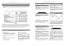
OPERATIONAL SPREADING CHART (Calibrated at 4 MPH ground speed)
. Since there is no agitator in the seed hopper, these materials will bridge at narrow seed gate settings and
cause erratic seeding rates. If bridging occurs at wider seed gate settings, cleaning the seed or blending with
a small dense seed such as clover may help. A mix of dry sand with the seed (50/50 mix) can sometimes solve
the problem.
The spread width indicated on this chart is possible if spinner is operated 30 inches above the
ground. Seeder should be level or tilted forward slightly.
NOTE:
Spread Chart settings are approximate – always make trial run to check actual application rate.
The amount of seed or fertilizer broadcast depends on the size of the hopper opening and the speed of the vehicle.
The table shown is an approximate guide based on a forward speed of 4 MPH, so adjust for different speeds. A for-
ward speed of 8 mph will cut above rates by one half. A speed of 6 mph will change rates by 75%.
NOTE:
HELPFUL TROUBLE-SHOOTING TIPS
1. Not feeding even –
A. Seed gate opening may be set too close for the
material being spread. To overcome, set the open-
ing larger and driver faster to obtain same spread
rate.
B. Check material for foreign matter or lumps.
C. Set screw loose or missing on fan hub.
D. Too windy for material being spread.
E. Operator not spacing spread runs properly for
correct overlap.
For best results, cover area twice over at one-half
recommended material usage rate, the second
time over to run halfway between first spreading
width or in a criss-cross pattern. This method
allows the most complete and even coverage, as
well as to give operator a chance to adjust gate
setting to compensate for too thin or too heavy a
covering the first time over.
2. Poor spread –
A. Spreader fan speed too slow (under 520 rpm) will
result in a narrow spread.
B. Bent or broken fan blades.
7
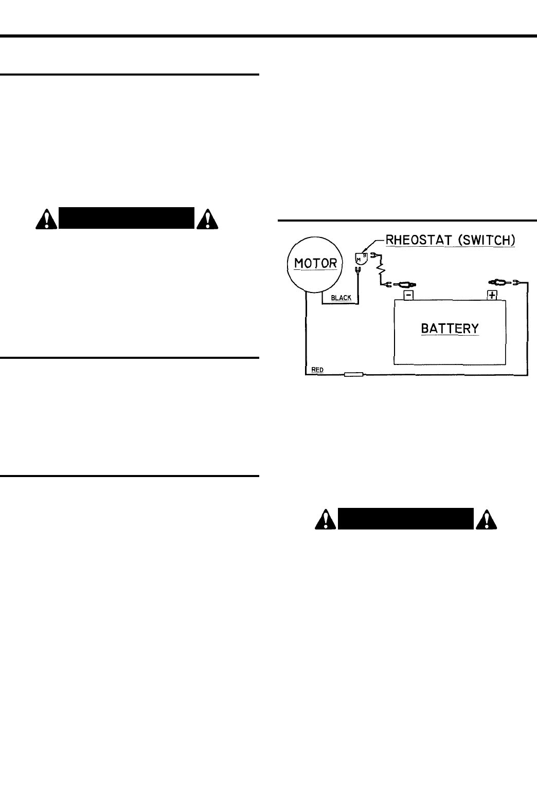
WIRING
Refer to the electrical schematic above. Strip approxi-
mately 1/2” of insulation from the ends of the wires and
crimp on the terminals as shown. For best results, solder
the connections using electrical grade solder. Attach the
wires to the rheostat switch and battery as shown.
When properly connected, the fan should rotate in a
clockwise direction, looking down on the fan. The first
position on the rheostat switch is full speed, which will be
used for most seeding applications. The second position
is variable speed, which can be used to reduce the
spread width.
The fan motor is for use on 12 volt electrical systems.
The motor will draw approximately 3 amps full load.
Some vehicle manufactures offer electrical access plug
assemblies as a convenience for attaching auxiliary elec-
trical equipment. (Honda consent assemble D.C.
#31650-958-681).
To prevent polarity problems, run both wires to the
battery, rather than grounding through the chassis frame.
NOTE: Always disconnect negative (–) cable first and
connect it last.
Always stop engine before disconnecting or
connecting battery cables or servicing battery.
CAUTION!