


24 Assembly
MAN0813 (3/17/2010)
ASSEMBLY
Assembly of this rotary tiller is the responsibility of the
WOODS dealer. It should be delivered to the owner
completely assembled, lubricated and adjusted for nor-
mal conditions.
Do not allow bystanders in the area when oper-
ating, attaching, removing, assembling, or servic-
ing equipment.
Do not modify or alter or permit anyone else to
modify or alter the equipment or any of its compo-
nents in any way.
Always wear relatively tight and belted clothing
to avoid getting caught in moving parts. Wear
sturdy, rough-soled work shoes and protective
equipment for eyes, hair, hands, hearing, and head;
and respirator or filter mask where appropriate.
SET-UP INSTRUCTIONS
The rotary tiller is shipped partially assembled. Assem-
bly will be easier if components are aligned and loosely
assembled before tightening hardware. See “Bolt
Torque Chart” on page 37 for recommended torque
values.
Complete the Pre-Delivery and Delivery Check Lists on
page 26 when assembly is complete.
Select a suitable working area. Refer to illustrations,
accompanying text, parts lists, and exploded view
drawings.
For reference, front, back, left, and right directions are
determined by sitting in the tractor operator’s seat.
DISASSEMBLE SHIPPING UNIT
It is advisable to have a mechanical lifting device to
facilitate uncrating.
Be careful of nails in boards when uncrating.
1. Remove all parts that are wired and strapped to
tiller and/or crate.
2. Remove top, sides, and ends of crate.
3. Remove front rubber shield from the bottom of the
crate (reverse rotation models only).
4. Remove lag screws from L-shaped shipping brack-
ets. Remove L-brackets from the tiller. Be sure to
save the mounting hardware for later use.
5. Remove tiller assembly from crate base.
6. Remove loose nails from boards and dispose of
crate according to local codes.
ASSEMBLY PROCEDURES
Required tools: 9/16", 3/4”, 1-1/8" combination
wrenches, sockets, torque wrench, and jack stands.
1. Lower skid shoes to lowest position and stand tiller
upright.
2. Use jack stands to support the front frame tube
with tiller sitting on the ground.
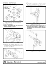
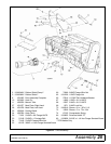
3. Install parking stand (33) and spring assembly to
tiller frame using 1/2NC x 3-1/4 cap screw (67) and
flange nut (62).
4. Unbolt lower hitch clevises (34), rotate 90 degrees,
and re-install in operating position, 26" from center
to center. Figure 23, page 25.
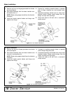
5. Install driveline (8) to gearbox input shaft.
6. Attach right mast plate (27) and driveline holder
(80) to gearbox frame using 3/8NC x 1-1/4 serrated
flange screws (83) and flange whiz nuts (60).
Attach driveline holder on outside of mast plate
using the front two holes. Use 3/8NC x 1 serrated
flange screws (55) and flange whiz nuts (60) to
attach mast plates (27 & 28) to gearbox stand in
remaining holes Figure 23, page 25.
7. Install CAT 1 quick hitch sleeve (70) using 3/4NC x
3-1/2 cap screw (68) and lock nut (69). Install in
the lower hole in the top of the mast plates.
8. Attach driveline tether chain to the tiller hitch frame.
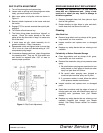
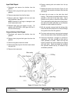
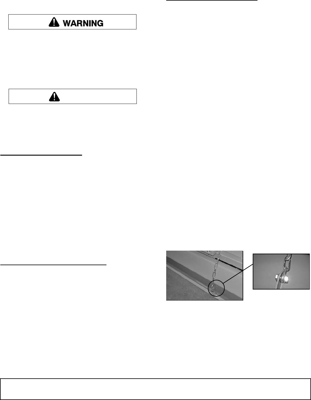
9. Attach tailgate chain to lug on tailgate using pack-
ing slip instructions in hardware bag. Thread the
chain through the keyhole slot on the top safety
shield support. Secure the chain by sliding the
desired link into the narrow portion of the keyhole
slot.
Figure 22. Attaching Tailgate Chain
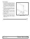
10. Attach front rubber deflector and clamp bar using
5/16NC x 1 carriage bolts (53) and flange whiz nuts
(54). (Reverse models only)
11. Fill gearbox with SAE 80W or 90W gear lube until it
runs out the center side level plug.
NOTE: Chain case has .8 quarts of 00 grease
installed at factory. This grease is very viscous and
will stick to chain at 70°F.
CAUTION
(Rev. 8/3/2011)