


12 Operation
MAN0813 (3/17/2010)
8. File and clean the cut ends of both drive halves.
Ensure the drive halves slide smoothly together.
Do not run the tractor if proper driveline engagement
cannot be obtained through these methods.
Connect the driveline to tractor PTO shaft, making sure
the spring-activated locking collar slides freely and
locks driveline to PTO shaft.
NOTICE
■ If attaching with quick hitch, the distance
between the tractor PTO and gearbox input shaft
will increase. Please follow the steps as you would
for a 3-point hitch to insure proper engagement.
WORKING DEPTH ADJUSTMENT
Keep all persons away from operator control
area while performing adjustments, service, or
maintenance.
1. Raise the tiller off the ground.
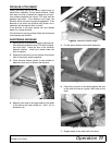
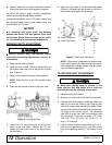
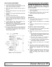
2. Level tiller side to side. Check by measuring from
the forward skid shoe pivot to the ground on each
side. (Figure 5)
3. Adjust, using tractor 3-point arm leveling device.
NOTE: Keep the front of the tiller parallel to the
ground.
4. Place two jack-stands under the tiller rotor shaft.
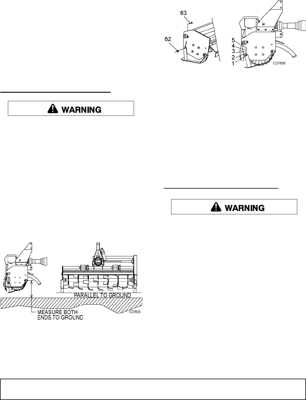
Figure 5. Leveling the Tiller
5. Loosen the 1/2” cap screws that act as the front
pivots to the skid shoes. Remove the 1/2” cap
screws (63) that hold the rear of the skid shoes to
the tiller frame.
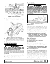
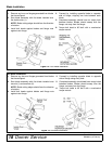
6. Adjust the skid shoe to the desired tilling depth
(Figure 6). Reinstall the cap screws in the rear of
the skid shoe and tighten all cap screws.
Figure 6. Tiller Depth Adjustment
NOTE: Tillage depth is dependent on ground hard-
ness, tractor speed, skid shoe setting, and tractor
hitch adjustment. Multiple passes may be neces-
sary to achieve tillage depth.
TILLER SIDE SHIFT ADJUSTMENT
■ Make sure parking stand is secured in the
down position and skid shoes are in hole one
before performing the following service work.
1. Disconnect tiller from tractor.
2. Measure rear tractor tire width (outside to outside).
3. Calculate side shift needed. Divide rear tractor tire
width by two and tiller width by two. Subtract tiller
width from tractor width and add five inches. Check
maximum tiller side shift capability on the specifica-
tion page of this manual, page 4. The calculated
side shift must be less than the maximum side
shift. (Example: Tractor rear tire width = 70”, TC60
Tiller = 60”. 70/2 = 35”, 60/2 = 30”. 35-30 = 5” + 5”
extra = 10” side shift.
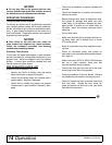
4. Loosen nuts on U-bolts on lower clevis hitch (4), U-
bolts on front gearbox stand (2), and bolts at the
back of the gearbox stand (2). See Figures 7 and
8.
Hole
First Pass
Depth
10”
21”
32”
43”
54”
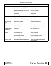
62 1/2NC Flange Nut
63 1/2NC Cap Screw
(Rev. 6/7/2011)