


Assembly 27
MAN0260 (8/6/2004)
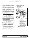
ASSEMBLY INSTRUCTIONS
DEALER SET-UP INSTRUCTIONS
Assembly of this mower is the responsibility of the
Woods dealer. It should be delivered to the owner com-
pletely assembled, lubricated, and adjusted for normal
cutting conditions.
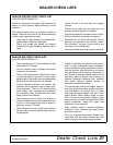
Complete Dealer Check Lists on page 31 when you
have completed the assembly.
The mower is shipped partially assembled. Assembly
will be easier if components are aligned and loosely
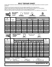
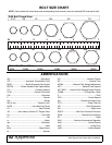
assembled before tightening hardware. Recommended
torque values for hardware are located on page 41.
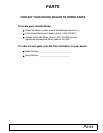
Select a suitable working area. Open parts boxes and
lay out parts and hardware to make location easy.
Refer to illustrations, accompanying text, parts lists and
exploded view drawings.
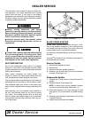
Before working underneath, carefully read Oper-
ator’s Manual instructions, disconnect driveline,
raise mower, securely block up all corners with
jackstands, and check stability. Secure blocking
prevents equipment from dropping due to hydrau-
lic leak down, hydraulic system failures, or
mechanical component failures.
Always wear relatively tight and belted clothing
to avoid entanglement in moving parts. Wear
sturdy, rough-soled work shoes and protective
equipment for eyes, hair, hands, hearing, and head;
and respirator or filter mask where appropriate.
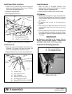
Uncrate Mower
1. Remove sides and top of mower shipping crate.
2. Remove lag screws and brackets that secure
mower to crate base.
3. Remove driveshaft wired to mower deck.
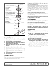
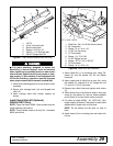
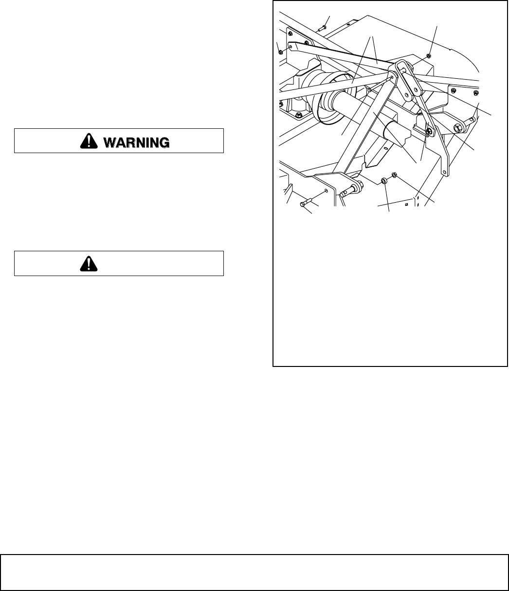
Install A-Frame Arms
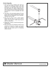
1. Loosen lock nuts (52) at lower hitch point and
install A-frame arms (13) as shown.
2. Tighten nut securely.
3. Repeat for opposite side.
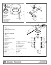
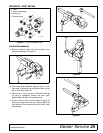
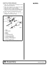
Figure 23. A-Frame Arms Installed
CAUTION
14
13
16
15
51
54
51
55
56
25
52
CD6497
13. A-frame arms
14. Rear offset link arms
15. Top link U-bracket
16. Sleeve 1-1/4 x 1-3/4 x 2-3/4
25. Sleeve 5/8 x 1 x 7/16
51. 1/2 NC Flanged lock nut
52. 5/8 NC Flanged lock nut
54. 5/8 Standard flat washer
55. 1/2 NC x 1-1/4 HHCS GR5
56. 5/8 NC x 2-1/2 HHCS GR5
(Rev. 1/13/2006)