


32 Assembly
MAN0475 (9/21/2005)
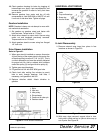
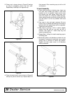
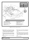
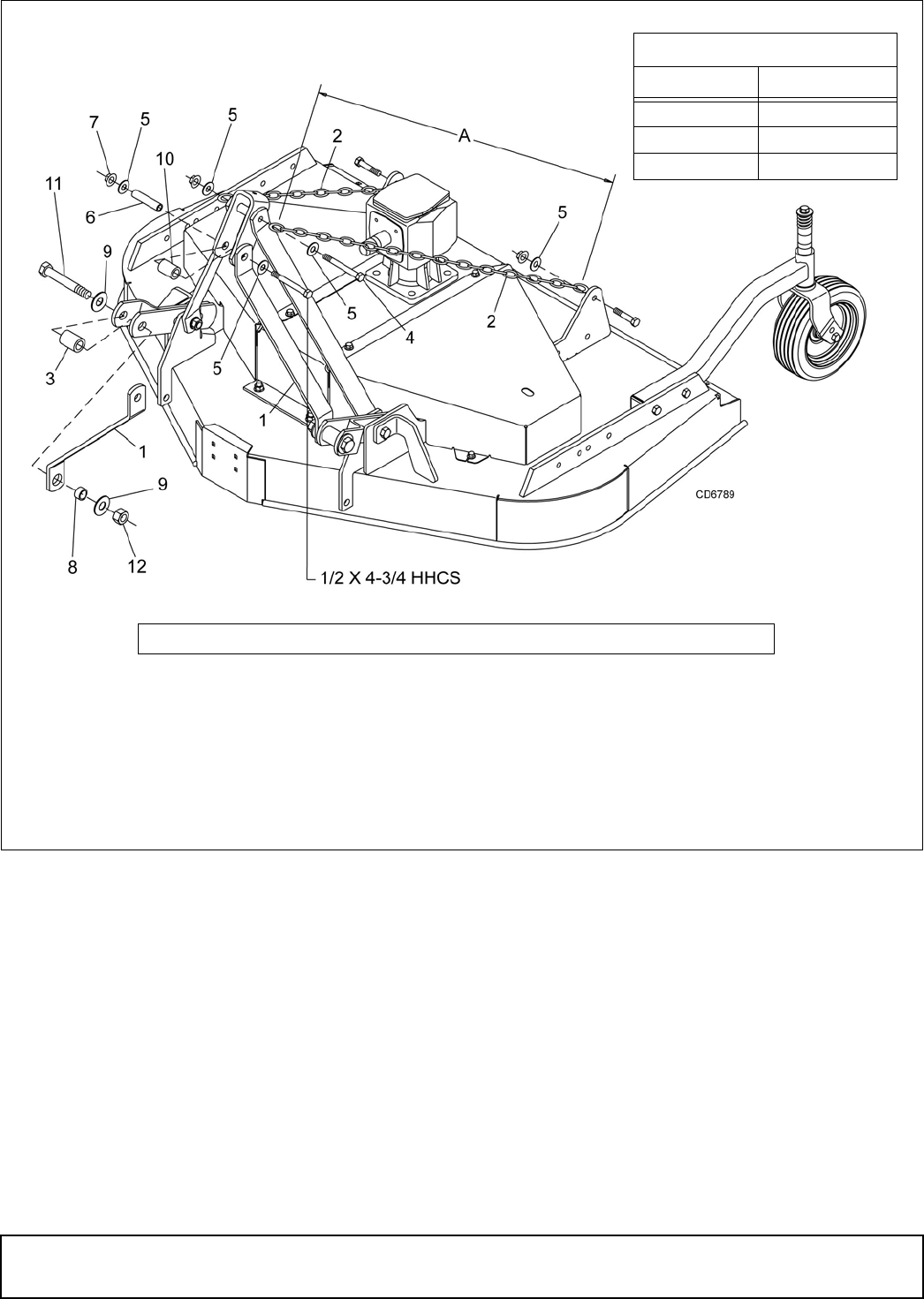
Figure 35. Quick Hitch Kit Installation (Optional)
3. Attach offset link (1) to lower hitch clevis using
sleeves (3 & 8), two flat washers (9), cap screw
(11), and hex nut (12) as shown in Figure 35. Do
not tighten hardware. Repeat for opposite side.
4. Attach upper end of offset links (1) to each side of
U-bracket link, using two flat washers (5), sleeves
(6 & 10), flange lock nut (7), and 1/2 x 4-3/4 cap
screw.
5. Remove rear offset links. They will be replaced
with chains (2)
6. Attach chains to top of A-frame on both sides as
shown, using cap screw (4), two flat washers (5),
and nut.
7. Attach opposite ends of chains (2) to rear mower
frame as shown. Cut chains to length (see chart
above). Vary length slightly as desired. Twist chain
to make finite adjustments in length until unit lifts
level.
8. Tighten all hardware.
1. Offset link, .38 x 2 x 15"
2. Chain, 3/8 proof coil 38-link
3. Sleeve, .94 x 1.44 x 1.94"
4. Screw, 1/2 NC x 6 HHCS GR5
5. Washer, 1/2" flat
6. Sleeve, .50 x .75 x 3.38"
7. Nut, 1/2 NC flange lock
8. Sleeve, 7/8 x 1-1/8 x 19/32" HT
9. Washer, 3/4 flat
10. Sleeve, .81 x 1.25 x 1.81"
11. Screw, 3/4 NC x 4-1/2 HHCS
12. Nut, 3/4 NC plated hex
CHAIN CUT-TO-LENGTH CHART
Model Dimension “A”
PRD6000 40"
PRD7200 45"
PRD8400 50"
NOTE:This kit is used on other models. Use only the hardware listed below.