


10 Assembly
29936 (Rev. 5/18/2007)
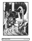
ASSEMBLY
Center Shield
To allow more lift on tractors with minimum ground
clearance, such as Fords, IH LoBoy, Kubotas, Satohs,
etc., a center belt shield is not offered. Refer to
page 24. If the box of parts has a center belt shield, bolt
center belt shield bracket (34) to deck with 3/8 x 1" bolt.
Bolt center shield (10) to bolts welded in deck and
bracket (34).
To provide clearance between tractor muffler and left
belt shield on L306, see page 24.
Side Skids
Bolt skids in such a position that they will be carried
close to the ground, but so they do not ride continually
on the ground when mower is operated at desired
mowing height.
On 59’s, use 3/8 x 1" heat-treated bolts (torque to 35
lbs-ft), lock washer and nuts. On L306’s, use 1/2 x
1-1/4" heat treated bolts, lock washers and nuts.
Front Toe Guard
Refer to page 24. Front toe guards (6) are furnished for
some mowers. When provided, bolt them to the front of
the mower, using 3/8 NC x 3/4" carriage bolts and 3/8"
flange lock nuts. (NOTE: On 59 and L59 where casters
are installed on outer deck rails, bolt toe guards to
mower so outer ends are about 2" in from end of deck.
Otherwise, end of toe guard will be about 1/2" in from
end of deck.) End of L306 toe guard will be 3/4" in from
end of deck.
Crosswise Rear Support
Refer to page 24. Install bushing (16) into center hole
in crosswise rear support and bolt it to back of mower
deck with short bar forward and offset up using 1/2 x 2"
hex head cap screw and 1/2" flange lock nut. NOTE:
On L59, L306F10-2, “S”, JD85, JD95, and GM4 mount-
ings, a special crosswise rear support is provided. If
tractor is equipped with turf tires, use upper center hole
in crosswise support, and for Ag tires, use lower hole.
See mounting frame drawing in those manuals.
Channel Arms
Refer to page 24. Slide mower under tractor. Attach
channel arms (12) to mower frame using 5/8 x 1-1/2"
clevis pin and safety pins. Pin crosswise rear support
bar (15) between channel arms and bolt center to
frame angle bracket as shown.
Casters
If casters are used, see page 27 or page 28, except for
the L59 mower on Ford 1000, 1600, 1700, 1900, and
Satoh S650. (See mounting frame drawing in manual.)
L306 caster assembly will not fit on IH424, 2424, 444,
2444, 454 and 2400; John Deere 1010 & 1020; Deutz
2506, 3006 and other tractors with swept back front
axle as they will hit front tires. Caster wheels cannot be
used on GM4 mounting.
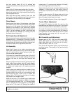
L306 Casters
On Ford 8N, Massey 135, Deutz 4006, IH 354, and
2300 with straight front axle, etc., the right caster
should be put on side angle, bolting it over side shield
and between side angle and right skid. Left caster
should attach to short bar on deck so casters will be
inside of left front tire. Left front tractor tire should be
moved out to clear caster wheel. On Ford 1000, Kubota
tractors, etc., both arms will bolt to the outer deck rails.
Caster wheels cannot be used on GM4 mounting.
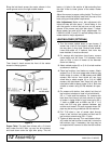
Front Roller Assembly Instructions
Refer to page 24. On 59 mowers, put item (28) on left
side and item (27) on right side of mower using 3/8"
carriage bolts and nuts.
On L306 mowers, item (28) goes on right side and item
(27) on left. This will put the highest hole in brackets
rearward on 59 and the next to the highest hole rear-
ward on L306.
Assemble roller and roller rod (26) in rear holes in
brackets (27 & 28). Secure with 3/16" cotter pins. Turn
roller by hand to see that it turns freely.
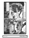
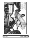
MOUNTING FRAME ASSEMBLY
Refer to page 18.
Idler & Mounting Bracket Assembly
Remove bolts holding front end of drawbar in place.
Slide idler bracket (6) between tractor wheel housings,
with idler slides rearward, and bolt to the center set of
holes in rear wheel housings, using holes in idler
bracket.
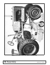
Use two 7/16" thick shims at each front hole between
the end plates and the tractor wheel housings. If nec-
essary, also use 5/8" flat washers. Assembly using
either 1/2" or 5/8 x 2-1/4 bolts and lock washers.
Idler Assembly to Idler Bracket
Install one V-groove idler (2) to left side of front verticle
slot by installing three 5/8" flat washers between idler