Assembly 35
MAN0763 (10/10/2008)
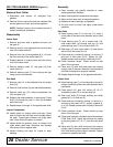
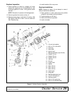
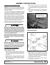
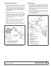
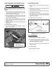
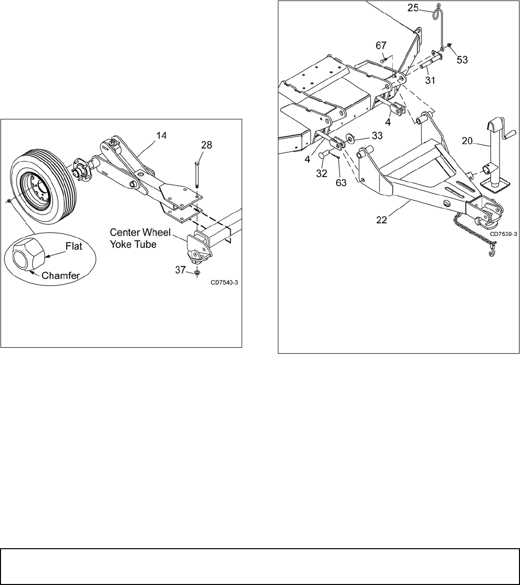
Install Spring Wheel Arms
1. Slide right spring wheel arm assembly (14) over
center wheel yoke tube and secure into position
using four cap screw (28) and flanged lock nut
(37). Repeat step to install left spring wheel arm
assembly. Keep spacing as wide as possible for
greater stability.
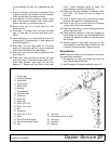
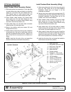
2. Attach wheels to hubs using five lug nuts. Install
the chamfered side of the lug nut toward the inside
for steel rim for pneumatic tires and rims. Tighten
to 75 lbs-ft. Check that tire air pressure is a
maximum of 40 psi.
NOTE: Install the flat side of the nut toward the
inside for solid tires and aircraft tires (shown).
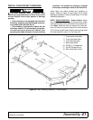
NOTE: Pneumatic, notat, and airplane tires are
available for this cutter. See page 61 for parts list.
Figure 24. Right Spring Wheel Arm Installation
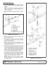
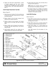
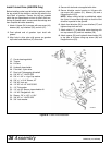
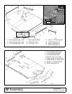
Install Tongue
1. Attach tongue (22) to center section using two
tongue pivot pins (31). Secure pivot pins to mast
plates using carriage bolts (67) and lock nuts (53).
NOTE: Attach hose holder (25) to right mast plate
with hardware shown.
2. Attach both attitude rods (4) to lower holes on
tongue and secure with clevis pin (32), washer
(33), and cotter pin (63).
3. Attach parking jack (20) to the side of the tongue.
Figure 25. Tongue Installation
14. Spring wheel arm assembly
28. 3/4 NC x 6 HHCS GR5
37. 3/4 NC Flange lock nut
4. Attitude rod
20. Parking jack
22. Tongue
25. Hydraulic hose holder
31. Tongue pivot pin
32. Clevis pin, 1" x 2.26"
33. Washer, flat 1"
53. 1/2 NC Flange lock nut
63. Cotter pin, 1/4" x 1-1/2"
67. 1/2 NC x 2 Carriage bolt


