Assembly 37
MAN0764 (11/5/2008)
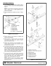
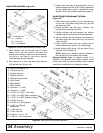
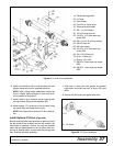
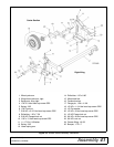
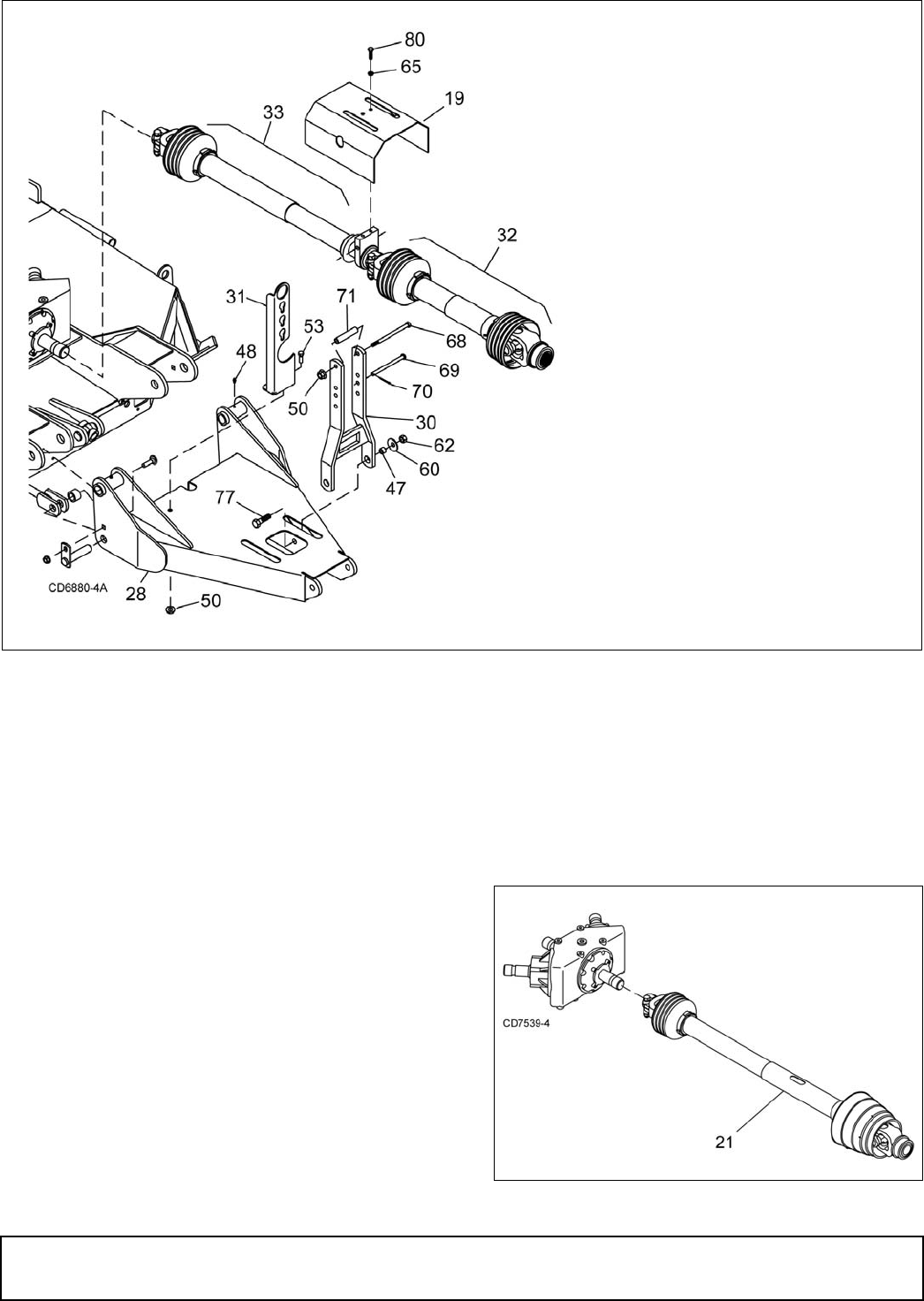
Figure 27. 3-Joint Drive Installation
6. Attach front driveline (32) to rear driveline (33) and
tighten clamp bolt and nut supplied with drive.
NOTE: With cutting height established, adjust the
3-joint H-frame bearing height so that front drive-
line is parallel to the ground.
7. Attach shield (19) to driveline carrier bearing with
two cap screws (80) and lock washers (65).
8. Attach spacer (71) to the top of the H-frame using
cap screw (68) and flange lock nut (50).
NOTE: See Figure 28 for optional CV drive installa-
tion.
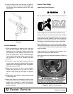
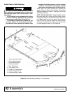
Install Optional CV Drive (Figure 28)
Before installing cutter input driveline to gearbox, check
the tag wired to the driveline and the tag wired to the
input shaft of gearbox. Ensure the tag rpm speeds
match the rpm speed decal on front of cutter. After con-
firming all speeds match, remove and discard tags and
then complete driveline assembly.
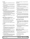
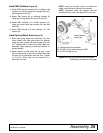
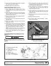
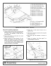
1. Align hole in drive yoke with groove on gearbox
input shaft and slide rear half of drive (23) onto
shaft.
2. Secure with bolt and nut supplied with drive.
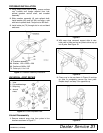
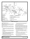
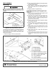
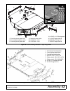
Figure 28. CV Drive Installation
19. Carrier bearing shield
30. H-Frame
31. Hose holder
32. Front 2/3 of 3-joint drive
33. Telescoping drive shaft
47. 5/8 x 1 x 9/16 Sleeve
50. 1/2 NC Flange lock nut
53. 1/2 NC x 1-1/4 Hex head cap
screw GR5
60. 5/8 x 1-3/4 x 14 ga Cup washer
62. 5/8 NC Lock nut
65. 3/8 Lock washer
68. 1/2 NC x 5-1/2 Hex head cap
screw GR5
69. 1/2 x 5-3/4 Clevis pin
70. 3/16 x 1 Cotter pin
71. Spacer, 1/2 x 3.56
77. 5/8 NC x 2 Hex head cap screw
GR5
80. 3/8 NC x 1 Hex head cap screw
GR5
21. CV Drive


