Dealer Service 25
MAN0680 (11/30/2007)
13. Slide shim (13) over input shaft (3) and secure with
snap ring (10).
14. Check input shaft end float by moving the input
shaft (3) by hand. If end float is higher than 0.012",
insert shim between input shaft (3) and rear
bearing (7). Repeat until end float is less than
0.012". Check rotational torque by hand. The
torque should be less than 2.2 lbs-inch.
15. Check that the gear backlash is between 0.006"
and 0.016". You should not have to adjust the
backlash.
16. Press in input oil seal (19), using tube of correct
diameter. Be careful not to damage seal lip.
17. Press oil cap (20) on to cover the rear of housing,
using a tube of the correct diameter.
18. Place top cover (22) on top of housing and secure
with six cap screw (23).
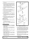
19. Check gearbox housing for leaks by plugging all
holes except one. Apply 4 psi compressed air and
immerse the gearbox in water to verify that there
are no leaks.
20. Remove gearbox from water and dry off with
compressed air. Add SAE 80W or 90W EP oil until
it runs out of side level hole. Tighten all plugs.
Reinstall Gearbox
NOTE: Gearbox is heavy: do not attempt to move with-
out mechanical assistance.
1. Set gearbox on cutter and fasten with bolts and
nuts. Torque bolts to 300 lbs-ft.
2. Attach crossbar (see Crossbar Installation, page
26).
CROSSBAR REMOVAL
1. It is necessary to gain access to bottom side of
cutter for crossbar removal. See BLOCKIiNG
METHOD, page 17.
NOTE: You will need to use either the puller screw
(Item 6, Figure 19) or a small hydraulic jack to
remove the crossbar.
2. Remove blade pin hardware, blade pins and
blades from crossbar.
3. Remove retaining wire from bottom of crossbar
and remove nut and washer.
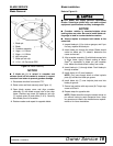
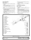
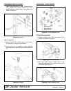
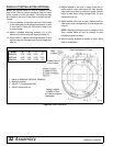
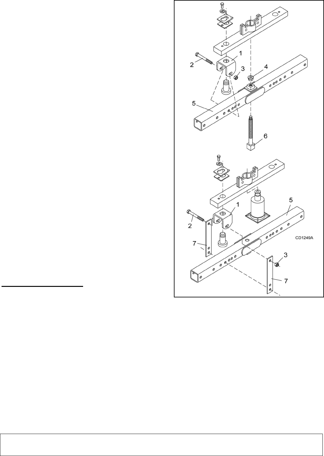
4. Refer to Figure 19. Attach clevis (1) to each end of
crossbar, using blade pins, spacers, keyhole
plates, and blade pin clips.
5. Position tube assembly (5) with threaded nut
toward crossbar for puller screw removal or down
for hydraulic jack removal.
Figure 19. Crossbar Removal
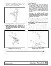
6. For removal with puller screw, attach tube (5) to
each clevis with bolts (2) and nuts (3). Place pad
(4) in nut and thread puller screw (6) into nut from
bottom. Tighten until pad is solid against gearbox
shaft. For best results, strike head of puller screw
with a hammer while tightening with a wrench.
7. For removal with a jack, attach tube to each clevis
with puller links (7), bolts (2), and nuts (3). Place
jack on tube with end of jack pressing against
gearbox shaft. Slowly apply force with jack.
NOTE: Hydraulic jack will not operate if tipped
more than 90°. Use care to prevent bending cross-
bar during removal.


