38 Assembly
MAN0654 (Rev. 10/19/2007)
ASSEMBLE BB840XP (PULL-TYPE)
Install Tailwheel Yoke
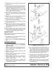
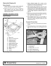
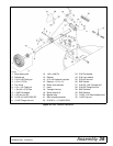
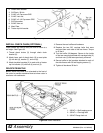
Refer to Figure 34.
1. Position pull-type wheel yoke (1) behind cutter with
cylinder lugs offset to the right.
2. Attach wheel yoke brackets to rear deck lugs using
two clevis pins, secure with cotter pins.
3. Attach wheel and hub using 1/2" x 3" bolts and 1/2"
nuts.
Install Attitude Rod
1. Place attitude rod into pivot block in wheel yoke.
The rod is a very tight fit; use care to prevent
thread damage.
2. Loosely install spacer, washer, and nuts on end of
attitude rod.
Install Height Adjustment Device
Ratchet
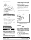
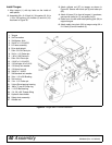
1. Place one end of ratchet (13) over lug on deck and
secure with pin (4) and cotter pins (6).
2. Attach opposite end of ratchet (13) over lug on
tailwheel and secure with pin (12) and two cotter
pins (6).
Cylinder
1. Place base end of hydraulic cylinder (14) around
lug on deck and secure with pin (4) and cotter pins
(6).
2. Extend cylinder rod, place transport lock bracket
(18) over cylinder rod end and around lug on
tailwheel.
3. Align holes of cylinder rod, transport lock bracket
and lug on tailwheel. Secure assembly using pin
(12) and cotter pins (6).
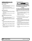
Install Hydraulic Hose
On pull-type units with optional hydraulic cut-
ting height adjustment, use a single-acting cylinder
with a maximum extended length of 28-1/4" (718
mm) from attaching point center to center.
NOTICE
■ If using a cylinder other than the one supplied
by Woods, make sure a breather fitting is installed
in the cylinder rod end port. Use a restricter fitting
in the base end port to dampen the cutter lowering
action.
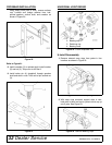
1. Install reducer bushing (15) and restricter elbow
(16) in port at base end of cylinder (14). Position
elbow to point toward front of cutter.
NOTE: Make sure there is a breather fitting
installed in the rod end port.
2. Connect hose (17) to elbow (16).
3. Install optional stroke control kit (19) to cylinder
rod. Stroke control kit is used to set cut height.
Install SMV Emblem
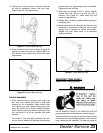
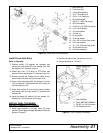
1. Align holes of manual tube (20) and SMV mounting
bracket (21) and attach both items to deck using
cap screws (22) washers (23), lock washers (24)
and hex nuts (25).
2. Attach SMV socket (26) to SMV mounting bracket
using two carriage bolts (27) and lock nuts (28).
3. Attach SMV emblem (29) to SMV bracket (30)
using two round head cap screws (31) and hex
nuts (32).
4. Insert SMV bracket (30) and emblem (29) into
socket (26).


