


2
WIRING
All wiring should be done in accordance with local and national electrical codes and ordinances.
If the boiler or burner manufacturer recommends a wiring
diagram, then follow such recommendations. If none is offered,
this diagram shows a suggested circuit.
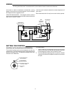
LOW LIMIT APPLICATION — This diagram shows a common
circuit on an oil fired heating system that also heats domestic hot
water which is stored in a tank.
Low limit control maintains domestic hot water temperature all
year round.
When thermostat calls for heat, burner and circulator operate.
T
1
4
2
3
T
5
6
T
T
THERMOSTAT
FIELD
INSTALLED
JUMPERS
TYPE
829A RELAY
CIRCULATOR MOTOR
LOW LIMIT
CONTROL
BURNER
MOTOR
HIGH LIMIT
CONTROL
IGNITION
TRANS.
TYPE 668 OIL
BURNER CONTROL
(LINE VOLTAGE)
HOT
LINE
N
SETTING THE CONTROL
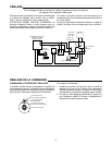
CONTROLS WITH ADJUSTABLE DIFFERENTIAL
The movable indicator points to the temperature at which the
contacts open. The fixed indicator points to the temperature at
which the contacts close. The difference between these two
indicators is the differential.
To set the control:
1. Use a screwdriver in the adjusting slot (A) on the front of the
control to turn the dial so that the fixed indicator (B) points
to the temperature at which the contacts will close.
2. Turn the differential adjusting screw (C) until the movable
indicator (D) points to the temperature at which the contacts
will open.
“B” FIXED INDICATOR
(CUT-IN POINT)
“C” DIFFERENTIAL
ADJUSTING SCREW
“D” MOVABLE INDICATOR
(CUT-OUT POINT)
“A” ADJUSTING
SLOT